
Mastering 3D Graphics Programming Basics
E N D
Presentation Transcript
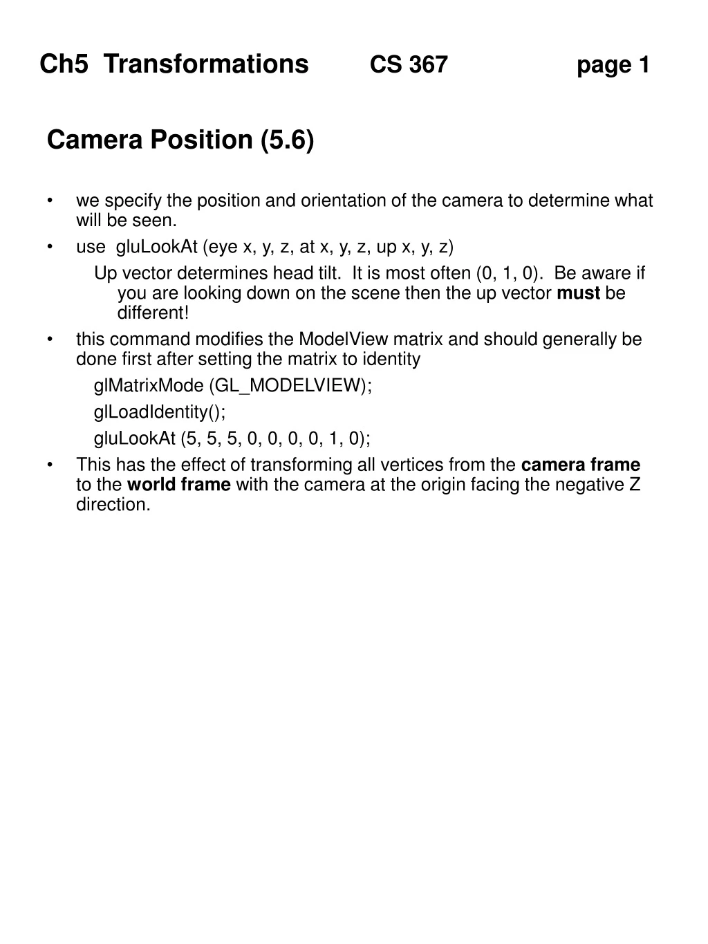
Camera Position (5.6) • we specify the position and orientation of the camera to determine what will be seen. • use gluLookAt (eye x, y, z, at x, y, z, up x, y, z) • Up vector determines head tilt. It is most often (0, 1, 0). Be aware if you are looking down on the scene then the up vector must be different! • this command modifies the ModelView matrix and should generally be done first after setting the matrix to identity • glMatrixMode (GL_MODELVIEW); • glLoadIdentity(); • gluLookAt (5, 5, 5, 0, 0, 0, 0, 1, 0); • This has the effect of transforming all vertices from the camera frame to the world frame with the camera at the origin facing the negative Z direction.
Projection • There are many different ways to draw 3D objects in drafting and freehand drawing. Computer graphics uses only two of them. Think of each projection as a different kind of lens on the camera. • Viewing Volume • Determines what will be seen. Objects (or portions of objects) not within the view volume will be clipped. • Parallel Projection / Orthographic • Preserves correct length even when objects are far away. This is an artificial projection but is useful for architects and engineers. • The viewing volume is a 3D box. • glMatrixMode (GL_PROJECTION); • glLoadIdentity(); • glOrtho (left, right, bottom, top, near, far);
Perspective • Perspective Projection • Creates foreshortening, the appearance that objects farther away are smaller. This is more realistic. • The viewing volume is a truncated pyramid called a frustum. • glMatrixMode (GL_PROJECTION); • glLoadIdentity(); • gluPerspective (view angle, aspect, near, far); • view angle is defined in degrees and can be considered a zoom lens 0 - 180 • aspect ration is width divided by height (1.0) • near and far should always be positive with respect to camera
Affine Transformations (5.3) • Skim 5.2 for background material on 2D transformations • Homogeneous Coordinates • 3D points are represented in 4D to make calculations easier • p(x, y, z, w) w is usually set to 1 • vector (x, y, z, w) w is usually set to 0 • Affine Transformations • convert one point into another • p’ = f(p) • different functions are used for different transformations • straight lines are maintained • rotation, scaling, and translation • apply to each point of an object • 4x4 matrices help to make the process more efficient • p’ = Mp • this is post multiplication • the book refers to points as a column [x y z w]T • Group Activity • P1 = (3, 5, 7, 1) • P2 = Identity * P1;
Translation • displaces a point a fixed amount in x, y, and z • shape and size remain the same • p’ = p + displacement • Translation matrix • 1 0 0 Tx • 0 1 0 Ty • 0 0 1 Tz • 0 0 0 1 • Group Activity • Tx = 3, y = 4, Tz = 5 • P1 = (1, 2, 3, 1); • P2 = Mt * P1;
Rotation • about an axis by a number of degrees • shape and size remain the same • positive rotation goes counter clockwise • parameters must be in radians • x’ = x cos(O) - y sin(O) • y’ = x sin (O) + y cos(O) • Rotate about X axis • 1 0 0 0 • 0 c -s 0 • 0 s c 0 • 0 0 0 1 • Different matrices for rotation about Y or Z
Scaling • generally about the origin • non uniform stretching along one or more axes • about a fixed point • if S > 1 then object gets bigger • Scaling matrix • Sx 0 0 0 • 0 Sy 0 0 • 0 0 Sz 0 • 0 0 0 1 • Group Activity • Sx = 1.5, Sy = 2.5, Sz = 0 • P1 = (2, 2, 2, 1); • P2 = M * P1; • Shear • We will not cover the shear transformation
Composing Transformations (5.3.2) • Concatenating matrices has the effect of applying one at a time • M = S Rx Ry Rz T • Note that matrices are multiplied in reverse order (right to left) • Warning! The order of concatenation makes a difference • Rotating about X and then Y is not the same as the inverse • A series of transformations is applied with concatenation • newObj = T * R * S * Obj • An alternative is to multiply the matrices only once to be more efficient • M = T * R * S • newObj = M * Obj • Rotation about a spcecific point instead of the origin • M = T R (-T)
Viewing Pipeline (5.6) • Several parameters must be provided to determine the final image: camera position, projection style and viewing volume. • Transformation pipeline • Keep in mind the transformations that all vertices go through and the order that it occurs. • display <-- projection <-- view <-- model <-- vertex • OpenGL has two built in transformation matrices: projection and modelview. Notice that the view and model matrices are combined into one. It is therefore critical to apply the view transformations BEFORE the model transformations.
Viewing Pipeline • objects re defined in modeling coordiates or object space (centered about the origin) • vertices are multiplied by the Model portion of the matrix to position the object in world space • vertices are then multiplied by the View portion of the matrix based on the position of the camera and converted to viewing space • vertices are multiplied by the projection matrix to create image space
OpenGL matrix operations • OpenGL maintains two global matrices • Projection - for projection paramters • Modelview - for transformation • All vertices are transformed before drawn. They are multipled by both matrices • Post multiplication is used, therefore you must perform the transformation in opposite order that you would expect • TRSp • Operations • glMatrixMode(GL_MODELVIEW) • glLoadIdentity() • glLoadMatrixf(M) • resets top matrix • glPushMatrix() • copy the top stack and place the copy on top • glPopMatrix() • replace the top matrix with the previous one • Concatenation • glMultMatrixf(M) • multiplies current Matrix times M
OpenGL • Transformations • glTranslatef(x,y,z) • multiplies current matrix to cause a translation • MV = MV * M • glRotatef(degrees, x, y, z) • multiplies current matrix to cause a rotation of the specified degrees about the specified axis. • glScalef(x, y, z) • multiplies current matrix to cause scaling about the X, Y, and Z axes
Small uisGL Example // look at ~grissom/367uisGL.h uisObject cube; uisMatrix M, S, T; // initialize structure from external object file infile.open(“cube.obj”); infile >> cube; // set transformation matrix from scene description file S.setScaling(x,y,z); T.setTranslation(x,y,z); M= T * S; cube.setTransformation(M); // transform all points at the beginning cube = M * cube; // render the object face by face
Hidden Surface Removal 5.5 • Backface Removal • You do not see the back side of an object. • Decision must be made on a face by face case with respect to the viewer position. • Hidden Surface Removal • the elimination of parts of objects that are obscured by other objects • Rotating Cube example from Ch 5.6 • Object Space algorithms attempt to dispaly objects in an appropriate order. (painters algorithm) • Image Space algorithms work on a pixel by pixel basis to determine which to display. The ordering of the objects is not important. (z-buffer)
Backface removal • Not covered in the book or by OpenGL • Identify which objects are facing towards the viewing • Calculate normal vector to face • Calculate vector from face to eye • Calculate the angle between the two • if greater than 90 then not visible • Use dot product, if <= 0 then not visible • uisGL Code uisObject Obj; uisFace F; uisVertex P1, P2, P3; uisVector V1, V2, N; V1 = P2 - P1; V2 = P3 - P1; N = V1 | V2; V1 = Eye - P1; if (V1 * N) <= 0 • not visible
Z buffer algorithm • Image space algorithm • maintain the z value for each pixel as a face is rasterized • only replace the current pixel with one that is closer to the viewer • this takes alot of memory called a Z -buffer • OpenGL does this for us • glutInitDisplayMode( GLUT_RGB | GLUT_DEPTH); • glEnable(GL_DEPTH_TEST); • glClear(GL_COLOR_BUFFER_BIT | GL_DEPTH_BUFFER_BIT); • We will use this method but it does not help in wireframe mode
Walking Thru A Scene • Notice the subtle difference between rotating the object compared to moving the viewer • run cubeview.c • Rotate cube with mouse • Move viewer with key presses x, X, y, Y, z, Z