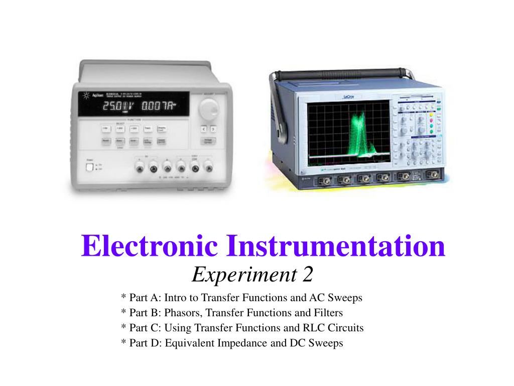
Experiment 2. * Part A: Intro to Transfer Functions and AC Sweeps * Part B: Phasors, Transfer Functions and Filters * Part C: Using Transfer Functions and RLC Circuits * Part D: Equivalent Impedance and DC Sweeps. Part A. Introduction to Transfer Functions and Phasors
Une image / un lien ci-dessous est fourni (tel quel) pour télécharger la présentation
Politique de téléchargement : le contenu du site vous est fourni TEL QUEL pour votre information et votre usage personnel ; il ne peut être vendu, concédé sous licence ni partagé sur d’autres sites sans l’accord de son auteur.Le contenu vous est fourni TEL QUEL, pour votre information et votre usage personnel uniquement.Téléchargez la présentation en cliquant sur ce lien.Lors du téléchargement, si vous ne parvenez pas à télécharger une présentation, l’éditeur a peut-être supprimé le fichier de son serveur.Pendant le téléchargement, si vous ne parvenez pas à obtenir une présentation, le fichier a peut-être été supprimé par l’éditeur.
F I N
Plus de contenu associé
Transcription de la présentation
Experiment 2 * Part A: Intro to Transfer Functions and AC Sweeps * Part B: Phasors, Transfer Functions and Filters * Part C: Using Transfer Functions and RLC Circuits * Part D: Equivalent Impedance and DC Sweeps
Part A • Introduction to Transfer Functions and Phasors • Complex Polar Coordinates • Complex Impedance (Z) • AC Sweeps
Transfer Functions • The transfer function describes the behavior of a circuit at Vout for all possible Vin.
More Complicated Example What is H now? • H now depends upon the input frequency (w = 2pf) because the capacitor and inductor make the voltages change with the change in current.
How do we model H? • We want a way to combine the effect of the components in terms of their influence on the amplitude and the phase. • We can only do this because the signals are sinusoids • cycle in time • derivatives and integrals are just phase shifts and amplitude changes
We will define Phasors • A phasor is a function of the amplitude and phase of a sinusoidal signal • Phasors allow us to manipulate sinusoids in terms of amplitude and phase changes. • Phasors are based on complex polar coordinates. • Using phasors and complex numbers we will be able to find transfer functions for circuits.
Review of Complex Numbers • zp is a single number represented by two numbers • zp has a “real” part (xp) and an “imaginary” part (yp)
Complex Polar Coordinates • z = x+jy where x is A cosf and y is A sinf • wt cycles once around the origin once for each cycle of the sinusoidal wave (w=2pf)
Now we can define Phasors • The real part is our signal. • The two parts allow us to determine the influence of the phase and amplitude changes mathematically. • After we manipulate the numbers, we discard the imaginary part.
The “V=IR” of Phasors • The influence of each component is given by Z, its complex impedance • Once we have Z, we can use phasors to analyze circuits in much the same way that we analyze resistive circuits – except we will be using the complex polar representation.
Magnitude and Phase • Phasors have a magnitude and a phase derived from polar coordinates rules.
Complex Impedance • Z defines the influence of a component on the amplitude and phase of a circuit • Resistors: ZR = R • change the amplitude by R • Capacitors: ZC=1/jwC • change the amplitude by 1/wC • shift the phase -90 (1/j=-j) • Inductors: ZL=jwL • change the amplitude by wL • shift the phase +90 (j)
Capture/PSpice Notes • Showing the real and imaginary part of the signal • in Capture: PSpice->Markers->Advanced • ->Real Part of Voltage • ->Imaginary Part of Voltage • in PSpice: Add Trace • real part: R( ) • imaginary part: IMG( ) • Showing the phase of the signal • in Capture: • PSpice->Markers->Advanced->Phase of Voltage • in PSPice: Add Trace • phase: P( )
Part B • Phasors • Complex Transfer Functions • Filters
Definition of a Phasor • The real part is our signal. • The two parts allow us to determine the influence of the phase and amplitude changes mathematically. • After we manipulate the numbers, we discard the imaginary part.
Complex Transfer Functions • If we use phasors, we can define H for all circuits in this way. • If we use complex impedances, we can combine all components the way we combine resistors. • H and V are now functions of j and w
Complex Impedance • Z defines the influence of a component on the amplitude and phase of a circuit • Resistors: ZR = R • Capacitors: ZC=1/jwC • Inductors: ZL=jwL • We can use the rules for resistors to analyze circuits with capacitors and inductors if we use phasors and complex impedance.
High and Low Pass Filters High Pass Filter H = 0 at w ® 0 H = 1 at w ®¥ H = 0.707 at wc wc=2pfc fc Low Pass Filter H = 1 at w ® 0 H = 0 at w ®¥ H = 0.707 at wc wc=2pfc fc
Corner Frequency • The corner frequency of an RC or RL circuit tells us where it transitions from low to high or visa versa. • We define it as the place where • For RC circuits: • For RL circuits:
H(jw), wc, and filters • We can use the transfer function, H(jw), and the corner frequency, wc, to easily determine the characteristics of a filter. • If we consider the behavior of the transfer function as w approaches 0 and infinity and look for when H nears 0 and 1, we can identify high and low pass filters. • The corner frequency gives us the point where the filter changes:
Taking limits • At low frequencies, (ie. w=10-3), lowest power of w dominates • At high frequencies (ie. w =10+3), highest power of w dominates
Taking limits -- Example • At low frequencies, (lowest power) • At high frequencies, (highest power)
Band Filters Band Pass Filter H = 0 at w ® 0 H = 0 at w ®¥ H = 1 at w0=2pf0 f0 Band Reject Filter H = 1 at w ® 0 H = 1 at w ®¥ H = 0 at w0 =2pf0 f0
Resonant Frequency • The resonant frequency of an RLC circuit tells us where it reaches a maximum or minimum. • This can define the center of the band (on a band filter) or the location of the transition (on a high or low pass filter). • The equation for the resonant frequency of an RLC circuit is:
Connexion au compte
Connectez-vous pour publier votre contenu sur SlideServe.