SEWER PIPING DESIGN
SEWER PIPING DESIGN Sewer piping differs from water piping, in that sewer pipes are not under pressure. The function that takes place inside sewer pipes is at ambient atmospheric pressure, and the influence of gravity.


SEWER PIPING DESIGN
E N D
Presentation Transcript
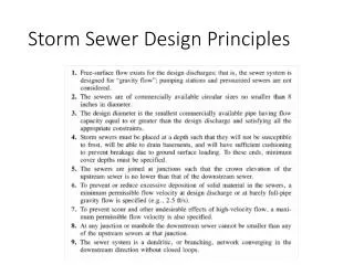
SEWER PIPING DESIGN Sewer piping differs from water piping, in that sewer pipes are not under pressure. The function that takes place inside sewer pipes is at ambient atmospheric pressure, and the influence of gravity. Sewer pipes drain because they are installed on a slope and fluids flow downhill. The slope of sewer lines is a consideration because most effluent floats, and slow movement of the drain allows solids to flow unobstructed. But if the flow is too rapid, larger solids tend to tumble, and become a potential for clogging a drain pipe. Ideally, a horizontal sewer drain is never more than half full. Drain lines that must traverse excessive height in a short lateral distance are installed with vertical drops rather than excessive slope.
Drain pipes are installed so the slope is consistent from the location of the fixture that is farthest from the entrance into a public drain, or to some suitable disposal. For this reason, the slope of drain pipes is critical to their efficiency. If a drain from a fixture in an intermediate area in a system is installed lower than the consistent point in the drain system, effluent will collect in the low areas, and the system will not drain well.
flow In addition to consistent slope, it is a requirement of the plumbing code for all turns in direction of piping be done with 45 degree fittings in the direction of flow, rather than 90. This facilitates the movements of slow moving solids through a drainage system.
CROSS SECTION THROUGH SINK OR LAVATORY DRAIN AND VENT Without a vent for supply of air to replace fluid in the drain, siphon action would pull the fluid out of the trap A vent provides a path to Expel toxic sewer gas to The atmosphere Non-integral trap Non-integral trap
WATER CLOSETS - Types of Discharge Blowout – Public - Loud Siphon Jet – Residential - Quiet The “seal” area in the diagrams indicate the integral trap. Because of the water that remains in the bowl, sewer gas is blocked from coming into the room .
The sizing of pipe for drainage is far less complex than that for water piping, as there is no pressure involved, no rate of flow of water, and distance makes a difference only in that enough slope must be available to accommodate the drainage. Three charts are pertinent to drainage. The first chart lists the fixture unit value for fixtures, which are not quite the same as for water supply fixture units.
The next chart shows the size of non-integral traps. A non-integral trap is a drain from a fixture to a building drain line, such as the drain mechanism beneath the lavatory in the bath room or beneath the sink in the kitchen. Non-integral means that the drain is not part of the fixture. An example of an integral trap is a water closet or a urinal, which have their own traps, because of the way they are made.
The third chart is the one related to determining the collective size of drain pipes in a system. The fixture unit values of each unit determines the size of each segment of pipe in the system that serves the fixtures. The logical sequence for determining pipe size is first to draw a plan of the building, showing all the fixtures that are to be installed. A line that represents the drain pipe is drawn to connect the fixtures, which extends out of the building to an available drain deposit, such as a municipal sewer system. Beginning at the “high” end of the system, the fixture unit value for each segment of pipe is shown. Then from the following chart, the size of drain pipe is found. The far left column indicates drain pipe diameter. Notice the top of the chart shows various degrees of slope for drain pipe. For this course, use the column that allows for a slope of ¼” per foot. The numbers in the body of the chart are total fixture units allowed by the pipe sizes for the slope given.
Remember that a Water Closet requires a 3” drain, and you cannot install more than two Water Closets on a 3” drain. A drain line that has more than two water closets must be a minimum of 4” diameter, regardless of how many fixture units it supports. The next slide shows the drainage plan for the residence that was used to calculate water supply. Realize that the drainage plan is to determine pipe sizes for what is called “rough plumbing,” which is that part of drainage that is installed below the floor and in walls. The smallest pipe generally used in rough plumbing is 2” diameter. Finish plumbing, or “trim” is the parts of the plumbing system one can see, beneath cabinets, under fixtures, etc., and is made of materials of a better finish for appearance and ease of cleaning.
The next sessions will include plumbing waste for fixtures that are stacked more than two story, and the method for determining vents and size of vents.