Download
1 / 67
780 likes | 1.41k Vues
This chapter covers the essential aspects of designing drainage systems within plumbing engineering. Topics include an overview of gravity flow and the waste and soil piping systems, as well as vent piping systems critical for efficient drainage. The chapter further discusses cold water piping systems, methodologies for estimating demand, and detailed pipe sizing techniques. A practical design exercise demonstrates the application of theoretical knowledge in real-world scenarios, ensuring a comprehensive understanding of drainage systems, including their components and calculations.

E N D
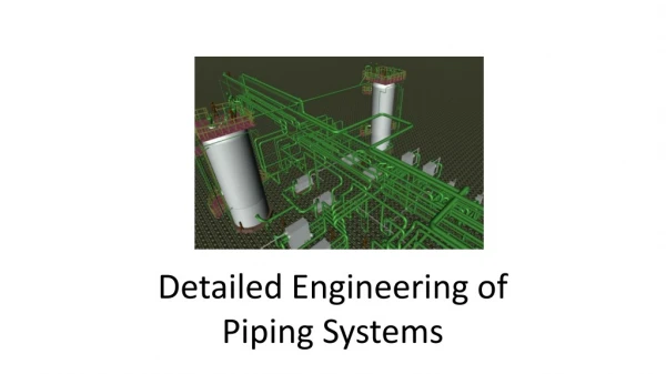
ME444 ENGINEERING PIPING SYSTEM DESIGN CHAPTER 8 : DESIGN OF DRAINAGE SYSTEM
LAST SESSION • COLD WATER PIPING SYSTEM • ESTIMATION OF DEMAND • PIPE SIZING • DESIGN EXERCISE
CONTENT • DRAINAGE SYSTEM OVERVIEW • GRAVITY FLOW • WASTE AND SOIL PIPING SYSTEM • VENT PIPING SYSTEM • DESIGN EXERCISE • STROM DRAINAGE
1. DRAINAGE SYSTEM OVERVIEW GRAVITY FLOW SEWER CW WASTE SOIL ACC RAIN RAIN DRAIN
TYPE OF SANITARY DRAIN WASTE • LAVATORY • SHOWER • FLOOR DRAIN • LAUNDRY • BATHTUB* SOIL (TREATED IN THE SEPTIC TANK FIRST) • WATER CLOSET • URINAL CLOSET • BIDET KITCHEN DRAINAGE NEED TO BE OIL/GREASE TRAPPED FIRST
COMPONENTS FLOOR DRAINS TRAP CLEAN OUT
2. GRAVITY FLOW • HORIZONTAL FLOW SHOULD HAS V > 0.6 m/s TO PREVENT SETTLEMENT • WATER DOES NOT COMPLETELY FILLS THE PIPE • IN VERTICAL FLOW WATER REACH TERMINAL VELOCITY IN 3 TO 10 METERS AFTER ENTRY • KEEP AIR INSIDE THE PIPE AT THE ATMOSPHERIC PRESSURE USING VENT PIPE
MANNING EQUATION FOR OPEN FLOW n = ROUGHNESS COEFFICIENT (USE 0.013 IN SEWAGE DESIGN) r = HYDRAULIC RADIUS (WETTED AREA/ WETTED PERIMETER) S = SLOPE (SI UNIT)
MANNING EQUATION FOR PIPE FLOW • FULL FLOW IN PIPE • VELOCITY DEPENDS ON SLOPE n = ROUGHNESS COEFFICIENT (USE 0.013 IN SEWAGE DESIGN) S = SLOPE
PARTIALLY FILLED PIPE Wetted area Wetted perimeter SpecifyA/pr2 and solve forh.
EQUATION FOR PIPE SIZING 25% filled 50% filled
PIPE INSTALLATION Use 45-degree connection to provide smooth flow.
TABLE 8.2 DRAINAGE FIXTURE UNIT (DFU) Drain Pipe Size Vent Pipe Size (DFU)
TABLE 8.2: MAX DFU FOR DRAIN PIPES *Not more than two WC. **Not more than six WC permitted.
4. VENT PIPING SYSTEM Purposes: • Prevents the loss of fixture trap seals. • Permits the smooth flow of water in the drainage system. Installation • Exit to outside air at least 2 meters above the roof. • Vent stack shall have uniform size.
WET VENT USE WASTE OR SOIL PIPE AS VENT PIPE
BACK VENT VENT AFTER FIXTURE’S TRAP
RELIEF VENT RELIEF PRESSURE FROM SOIL STACK EVERY10 FLOORS
VENT PIPE SIZING • For vent stacks, use the total DFU load for the drainage stack and the full developed length of the vent to find the size from TABLE 8.5. Vent stacks must be undiminished in size for their entire length. • For branch vents, use the longest developed length from the point where the size is being determined to the farthest connection to the waste line. Use TABLE 8.5 to find the size. • For individual fixture use TABLE 8.3.
If this building has 7 floor made up 25 m of height. Each floor has one toilet as previously designed. Size S W and V main pipes
SOIL system Each toilet has 44 DFU of soil x 7 floors = 308 DFU from table 8.4 DN100 can carry 500 DFU select DN100 WASTE system Each toilet has 26 DFU of waste x 7 floors = 182 DFU from table 8.4 DN100 can carry 500 DFU select DN100
VENT system Each toilet has 70 DFU x 7 floors = 490 DFU the total length of vent pipe is approximately 25m vertical + 12m horizontal = 39m From Table 8.5, DN80 vent pipe can carry 500 DFU at 55m of length Select DN80