Piping System Development
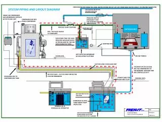
Piping System Development. Piping System Design Flowchart. Typical Building Layout. Piping System Design Flowchart. Determine Loads and Consult References. Piping System Design Flowchart. Determine the system to be used and develop a concept for part-load control.

Piping System Development
E N D
Presentation Transcript
Determine the system to be used and develop a concept for part-load control
FCU : fan coil unit is a simple device consisting of a heating or cooling coil and fan. It is part of an HVAC system found in residential, commercial, and industrial buildings. • PAU: A programmable arithmetic logic unit for performing high speed bit sliced, pipelined computations at very low power is fabricated as an LSI component using CMOS/SOS technology. It is microprogrammable and operates in conjunction with a fast microprogram store program memory and controller. Dual input ports which supply data from eight sources are latched and operated on while new data is simultaneously fetched. Instruction bits shift data in either port left or right, select complements and select an operand between device input and output data in one port. The data processed in each port is compared and is added to provide a latched tri-state output to an external device
AHU: air handling unit is a device used to condition and circulate air as part of a heating, ventilating, and air-conditioning (HVAC) system. An air handler is usually a large metal box containing a Blower, heating or cooling elements, filter racks or chambers, sound attenuators, and dampers. Air handlers usually connect to ductwork that distributes the conditioned air through the building and returns it to the AHU. Sometimes AHUs discharge (supply) and admit (return) air directly to and from the space served without ductwork.
Sources • ASHRAE Hong Kong Chapter