Download
1 / 14
140 likes | 246 Vues
This presentation delves into systematic resonance compensation in the PS Booster accelerator. The first part covers the motivation, history, and correctors in the PSB, while the second part discusses optics measurements for compensation optimization. The talk details the evolution of resonance compensation strategies, including empirical optimizations and minimizing driving terms. It also explores past resonance compensation efforts, recent developments, and the alignment campaign before LS1. The concept of resonance compensation using lenses of proper types for various errors is explained, along with practical examples. The text concludes by highlighting the challenges and complexities of compensating multiple lines simultaneously.

E N D
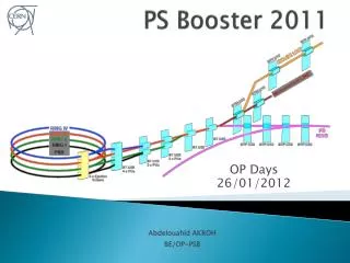
Resonance compensation in the PS Booster (1st part) E. Benedetto + M. McAteer (2nd part) BE/ABP • Presentation based on: old reports by K. Schindlet al. (available in EDMS), email exchanges between B. Mikulec & M. Chanel, S. Pittet, A. Newborough, PhD thesis of P. Urschutz, material from V. Forte, many discussion & coffees with C. Carli
Outline First part (Elena): • Motivation • A bit of history… • Correctors in the PSB • Example: correcting the half integer line with QNOs Second part (Meghan): • Optics measurements for systematic resonance compensation
Introduction • To reach high brightness and intensity beams, minimizing emittance blow-up and losses • Large space-charge tune footprint at injection • Touches many resonance lines • Not all of them are excited, but if so they need proper compensation • Compensation: • Empirical optimization w.r.t. losses (based on optics considerations) • From optics measurements, minimization of the resonance driving terms P. Urschutz, tune footprint evolution for high intensity beams, “low” working point
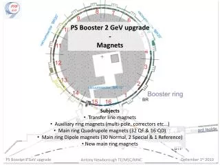
A bit of history… • Resonance compensation done already in the late 70ies: • K. Schindl et al., ‘78,-’79 • Working Point was (4.26, 5.55) • Installation of a “new” extra set of multipoles in ’77 to allow simultaneous correction of more then one line (3rd order). • New campaign in 2003-2004 • P. Urschutz, PhD thesis • Measurements of resonance driving terms with turn-by-turn PUs (expert set-up) • Validated choice of moving WP to (4.26, 4.55) to avoid systematic 3Qv=16 • Optimization w.r.t. losses by M. Chanel and OP • Alignments (errors!) change during time, realignment campaign LS1… • Program of measurements (by Meghan) to build up an optics model for the PSB, will lead to a systematic resonance compensation scheme
Correctors in the PSB • Steerers (dipolar errors, i.e. COD) • QNO, QSK(quadrupolar normal/skew) • XNO, XSK (3rd order normal/skew) • ONO, OSK (4th order, not used) • Harmonic correctors: • ONOHO Landau Damping (not used), • XNOHO chromaticity (used in MDs), • QSKHO Coupling
Correctors in the PSB • The same unit combines different correctors (x4 rings) e.g. sitting in 12L1 e.g. sitting in 11L4
Correctors in the PSB • Big improvement w.r.t. last years: • Connected to Acapulco power supplies (except ONOHO and XNOHO) • Controlled by FGC3 • Allow change of polarity in PPM and individual trimming
Resonance compensation For compensating a particular resonance m Qx + n Qy = p, it is sufficient to have 2 lenses of the proper type, provided the betatron phase advance is near: 90o+k*180o(k integer) with respect to the harmonic p considered • E.g. to compensate a dipole error (COD) • 2 steerers located at 90o+k*180ow.r.t. each other provide an orthogonal set • To compensate a field error: • 2 QNOs located at 45o+k*90o • etc… for higher order
Resonance compensation • Quadrupolar error (half integer line, Qy=4.5) • Normal quadrupoles QNOs • QNO4 and QNO8 are located at Dm=Qy/4=1.125 (x 2p = 45o +k90o) OK! • Actually…QNO412L3, QNO816L3: • Powered in series QNO4-QNO12 and QNO8-16 • Opposite polarities • WHY? • Dm(4-12)=4.5/2=2.25 (x 2p = 90o +k90oi.e. 180o with respect to p=2) • as they have opposite polarity, the effect adds up • Being focusing & defocusing, no changes in the tune • Moreover, considering effect on the integer (Qv=4.0): • Dm(4-12)=4.0/2=2.0 (x 2p = 0o i.e. 360o with respect to p=2) as they have opposite polarity, the effect on the integer line cancel out + QNO8L3 - + QNO4L3 QNO12L3 QNO16L3 -
Summary • Qualitative considerations • Example on how to compensate one single line (2nd order) • Compensation of one line leads to excitation of a second line • More than 2 lenses are needed • More complicated when moving to higher order and to several lines at the same time • More systematics measurements and knowledge of the optics model is needed Meghan