Download

1 / 15
150 likes | 388 Vues
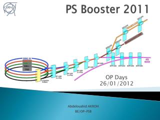
Space Charge in the PS Booster. E. Benedetto Contributions from: C. Carli, V . Forte, M. Kowalska , M. Martini, M. Mc Ateer , B. Mikulec , V. Raginel , G. Rumolo. 20/5/2014 Space Charge Collaboration Meeting 2014. Outline. Intro PS Booster description & Upgrade plan

E N D
Space Charge in the PS Booster E. Benedetto Contributions from: C. Carli, V. Forte, M. Kowalska, M. Martini, M. Mc Ateer, B. Mikulec, V. Raginel, G. Rumolo 20/5/2014 Space Charge Collaboration Meeting 2014
Outline • Intro PS Booster description & Upgrade plan • Measures against Space Charge • Space Charge studies for the PS Booster • Machine modeling • Computing time
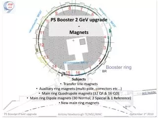
PSB parameters Circumference: 157m Super-periodiciy: 16 Injection: conventional Multi-Turn upgrade to H- Injection energy: 50 MeV upgrade to 160 MeV Extraction energy: 1.4 GeV upgrade to 2 GeV Cycle length: 1.2s # bunches: 1 x 4 Rings RF cavities: h=1+2, h=16 Tunes at injection: 4.30, 4.45, ~1e-3 Rev. freq. (160 MeV): ~1MHz # protons/bunch: 50 1000 x 1e10 H. emittance: 2 15 um V.lemittance: 2 9 um Longitud. emittance: 1 1.8 eVs
Space Charge limitations in the PSB B. Mikulec, et al, HB 2012 • Very large tune spread at injection • Up to 0.4 for LHC beams • > 0.7 for high intensity (with losses) Injection energy upgrade: • From 50 to 160 MeV: • 2x intensity (for given emittance) • 1/2 x emittance (for the same intensity) • Or a combination …
Measures against Space Charge • Double harmonic: h1+h2 • Acceleration (no energy flat bottom) • H- injection directly on accelerating bucket • Today: MT injection in coast, then adiabatic capture + acceleration • Transverse painting: • Horiz. Painting + Vert. Steering • Today: injection offset in both planes (V steering and delay of the bump decay wrt injection timing) • Working point varies with time • Resonance compensation: • Empirical (based on loss reduction and driven by phyiscs considerations) • Systematic studies driving terms and response matrix ongoing (M. McAteer)
Areas of investigation • Emittance preservation for LHC beams (increased brightness) • e.g. during fall of H- inj chicane bump • Losses control for high intensity beams (increase intensity) • More activation with increased energy • See Magda’s talk • Multi-Turn injection dynamics (both present and H-) • Must include Space Charge Np=3.4e12 (=2x today) Ex=1.72 um Ey=1.72 um (LIU Parameters, EDMS-1296306) Np > 1.e13 (today nominal) Ex= 15 um Ey= 9 um • Benchmark Simulations w. Measurements & Theory • See Vincenzo’s talk Optics Model (via response matrix and driving terms)
Studies of emittance preservation - BSW1 - BSW2 BSW3 BSW4 Perturbation from chicane magnets Edge effects (rectangular magnets) Corrugated Inconel vacuum chamber new baseline (ceramic in the original design) induced Eddy currents: • Delay of ~50us • Higher order field components (sextupolar) • Quadrupolar feed-down • Excitation 3rd order resonance 3D magnet simulation by B. Balhan, J. Borburgh Chicane ramp-down shape by D. Aguglia, D. Nisbet
Studies of emittance preservation • Simulations with PTC-Orbit: • Time varyingelements • Acceleratingbucket • Double harmonic • Optics model as simple as possible • No errorsexcept in BSW magnets Ceramic chamber Inconel, wo correction Inconel, all corrected. • Results are validin relative, to discriminatebetweenceramic and inconel chamber • No showstoppers for inconel chamberfound, but compensation isrequired • additionaltrims on main quads QDE3, QDE14
Multi Turn injection (present scheme w. septum) • Differences in beam profiles and losses if space charge is (not) included in the simulations w/o space Charge with space Charge 4th turn 4th turn 0th turn 0th turn 20th turn 60th turn 20th turn 60th turn V. Raginel et al. , CERN note 2013 and PAC’13
Machine modeling and benchmark • Very good agreement between measurements & simulations when machine model (misalignments and field errors) is implemented Simulations close to the 0.5 line, beam intensity evolution See V. Forte’s talk
Computing time Reasonably “short” time scales PTC-Orbit (migration to PTC-pyOrbit in summer) Time on our CERN cluster: • Chicane decay ~7ms=~ 7’000 turns 8 hours • Benchmark with measurements ~200ms >2 weeks (continuous tracking, i.e. dump & load for restart) • High intensity & emittance beams x2 time (increase # macroparticles) # SC nodes: ~200 # macroparticles: 250k 500k
Conclusions • Goal: improve understanding of current Space Charge limits and predict PSB performance with the new H- injection • LHC (high brightness) beams emittance preservation • High Intensity beams losses control • Multi-Turn (conventional or H-) process itself • Benchmark code vs. measurements, was our major effort of MDs in 2012-2013 • Optics model (response matrix and driving terms) studies ongoing in //, the aim is to implement resonance compensation scheme • Knowledge of optics model fundamental for accurate prediction of Space-Charge induced losses and beam blow-up
Curve emittance vs. Intensity B. Mikulec et al.