Download
1 / 92
980 likes | 1.36k Vues
Defining, Desiging and Evaluating Digital Communication Systems. Jacek Ilow, Ph.D. Associate Professor. Department of Electrical and Computer Engineering Dalhousie University Halifax,Canada. J.ilow@dal.ca http://www.dal.ca/~jilow http:// radio-1.ee.dal.ca/~ilow.

E N D
Defining, Desiging and Evaluating Digital Communication Systems Jacek Ilow, Ph.D. Associate Professor Department of Electrical and Computer Engineering Dalhousie University Halifax,Canada J.ilow@dal.ca http://www.dal.ca/~jilow http://radio-1.ee.dal.ca/~ilow
Multilevel PSK and QAM constellations PSK with M=4 and M=8 and M=16 QAM constellations 16-QAM constellation Note the non-constant envelope Question: based on these constellation diagrams, which one has the better error rate performance? Question: based on these constellation diagrams, which one is better? Better is what sense: (i) bit error rate performance; (ii) bandwidth utilization; (iii) implementation complexity? 16-QAM constellation Note the non-constant envelope
Cost Cost, power & BW efficiencies: Examples • Microwave links: • high bandwidth efficiency • moderate cost efficiency (links can cost a lot) • moderate power efficiency (beaming easy) • Wireless mobile systems: • power, bandwidth and cost efficiency very important • earlier bandwidth efficiency was easiest to compromise • nowadays signaling rates increase and bandwidth efficiency is becoming more and more important issue Power Bandwidth Cost Power Bandwidth
Modulation Tradeoffs • Want high rates, high spectral efficiency, high power efficiency, robust to channel, cheap. • Linear Modulation (MPAM,MPSK,MQAM) • Information encoded in amplitude/phase • More spectrally efficient than nonlinear • Issues: differential encoding, pulse shaping, bit mapping. • Nonlinear modulation (FSK) • Information encoded in frequency • Continuous phase (CPFSK) special case of FM • Bandwidth determined by Carson’s rule (pulse shaping) • More robust to channel and amplifier nonlinearities
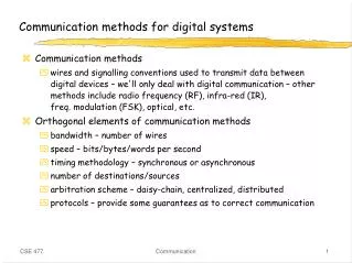
Digital vs. Analog Communications • Analog and Digital Signals • Messages are digital or analog. • Digital messages are constructed with a finite number of symbols. For example, a text file is a digital message constructed from 50 symbols, consists of 26 letters, 10 numbers, a space and several punctuation marks. Similarly, a Morse-coded telegraph is a binary message, implying only two symbols – mark and space. • Analog messages are characterized by data whose values vary over a continuous range. For example, a speech waveform has amplitudes that vary over a continuous range. A picture is also an analog message.
Digital Transmission • Current trend: digital transmission. • Cost efficient: advances in digital circuitry (VLSI). • Advantages: • Data integrity: better noise immunity. • Security: easier to integrate encryption algorithms. • Channel utilization: higher degree of multiplexing (time-division mux’ing).
Digital vs. Analog Communications • Noise immunity of digital signals – digital data can be recovered without any error as long as the distortion and noise are within limits. On the other hand, for an analog message, even a slight distortion or interference in the waveform will cause an error in the received signal. • Regenerative repeaters––Based on this “noise immunity”, when transporting a bit stream over a long distance, regenerative repeaters or repeater stations are placed along the path of a digital system at distances short enough to ensure that noise and distortion remain within a limit. The viability of regenerative repeaters is the main reason for the superiority of digital systems over analog ones.
A Basic Digital Communications System(with an ARQ Feedback Channel???) Digital Input Stream Source Encoder Channel Encoder Digital Modulator Turn into continuous wave Remove Redundant bits Add controlled redundancy for error correction Received data OK/ NOT OK via Feedback Channel Channel Noise Q: Why bother with FEC When we have ARQ? Channel Decoder (+check) Digital Output Stream Source Decoder Digital De-modulator Turn back into binary symbols Reconstruct original bit sequence Remove redundant bits. Check data
Building a Digital Communications System • Source coding (data compression): the process of efficiently converting the output of a source into a sequence of binary digit. • Channel coding The introduction of redundancy in the information sequence for the purpose of combating the effects of noise and interference in the channel. • Modulation A process that converts the digital information sequences into waveforms that are compatible with the characteristics of the channel. • Channel estimation Generally, channels may introduce distortion to the source signal, and the characteristics of the channel/distortion need to be estimated or identified at the receiver end, in order to reduce or eliminate the distortion and recover the original signal. This is called channel estimation or identification.
Embedded uP FPGA Dedicated FSM Dedicated DSP Reconfigurable DataPath Implementation Targets
Host Host application application transport transport network network data link data link physical physical Bridge/Switch data link MAC (data link) physical physical physical data flow The Context – communication devices and underlying networks WAN LAN Router network protocol data link physical e.g. PSTN – modem, satellite, TDM point-to-point leased line ATM, Frame Relay, X.25, CDMA (e.g. CDMA-1X), etc. e.g. Gigabit Ethernet - fibre optic cable • e.g. 100BaseTx • CAT 5, 802.11
“Bottlenecks” of RF/DSP Designs • Interdisciplinary knowledge • Lack of Tools(Simulation &Design) • Tradeoff of Multiple parameters
Introduction to Digital Modulation • Most information today is in bits • Baseband digital modulation converts bits into analog signals (typically bits encoded in amplitude) • Passband digital modulation has form • Bits encoded in amplitude An, phase n, or frequency n=2p(fn-fc)t, which are constant over a bit time Tb. 1 0 1 1 0 1 0 1 1 0 On-Off Polar Tb t t
ASK, PSK, and FSK • Amplitude Shift Keying (ASK) • Phase Shift Keying (PSK) • Frequency Shift Keying 1 0 1 1 m(t) AM Modulation 1 0 1 1 m(t) AM Modulation 1 0 1 1 FM Modulation
r(nTb)+N DN r(nTb) ASK/PSK Demodulation • Similar to AM demodulation, but only need to choose between one of two values • Decision device determines which of r0 or r1 that r(iTb) is closest to • Noise immunity DN is half the distance between r0 and r1 • Bit errors occur when noise exceeds this immunity Decision Device nTb r1 “1” or “0” r(nTb) s(t) r0 cos(2pfct)
Modulation Process • Modulation implies varying one or more characteristics (modulation parameters a1, a2, … an) of a carrier f in accordance with the information-bearing (modulating) baseband signal. • Sinusoidal waves, pulse train, square wave, etc. can be used as carriers • Why Carrier? Effective radiation of EM waves requires antenna dimensions comparable with the wavelength: • Antenna for 3 kHz would be ~100 km long • Antenna for 3 GHz carrier is 10 cm long • Sharing the access to the telecommunication channel resources
Carrier: A cos[t +] A = const = const = const Amplitude modulation (AM) A = A(t) – carries information = const = const Frequency modulation (FM) A = const = (t)– carries information = const Phase modulation (PM) A = const = const = (t) – carries information Continuous Carrier
Modulation Considerations • Want high rates, high spectral efficiency, high power efficiency, robust to channel, cheap. • Linear Modulation (MPAM,MPSK,MQAM) • Information encoded in amplitude/phase • More spectrally efficient than nonlinear • Easier to adapt. • Issues: differential encoding, pulse shaping, bit mapping. • Nonlinear modulation (FSK) • Information encoded in frequency • More robust to channel and amplifier nonlinearities
Frequency Shift Keying (FSK) Baseband Data 1 0 0 1 BFSK modulated signal f0 f0 f1 f1 where f0 =Acos(c-)t and f1 =Acos(c+)t • Example: The ITU-T V.21 modem standard uses FSK • FSK can be expanded to a M-ary scheme, employing multiple frequencies as different states
Phase Shift Keying (PSK) Baseband Data 1 0 0 1 BPSK modulated signal s0 s0 s1 s1 where s0 =-Acos(ct) and s1 =Acos(ct) • Major drawback – rapid amplitude change between symbols due to phase discontinuity, which requires infinite bandwidth. Binary Phase Shift Keying (BPSK) demonstrates better performance than ASK and BFSK • BPSK can be expanded to a M-ary scheme, employing multiple phases and amplitudes as different states
Geometric Representation • Digital modulation involves choosing a particular signal si(t) form a finite set S of possible signals. • For binary modulation schemes a binary information bit is mapped directly to a signal and S contains only 2 signals, representing 0 and 1. • For M-ary keying S contains more than 2 signals and each represents more than a single bit of information. With a signal set of size M, it is possible to transmit up to k=log2M bits per signal.
Geometric Representation 2 • Any element of set S can be represented as a point in a vector space whose coordinates are basis signals j(t) such that
Example: BPSK Constellation Diagram Q I Eb -Eb Constellation diagram
d Geometric Signal Representation • Transmit symbol mi{m1,…mM} • mi corresponds to signal si(t), 0tT • Represent via orthonormal basis functions: • si(t) characterized by vector si=(si1, si2,…,siN) (Vector space analysis) s3 s2 s1 s4 s8 s5 s6 s7
-A A 3A -3A -A -3A -5A
QPSK Constellation Diagram Q Q 01 00 I 11 I 10 • Quadrature Phase Shift Keying has twice the bandwidth efficiency of BPSK since 2 bits are transmitted in a single modulation symbol Carrier phases {0, /2, , 3/2} Carrier phases {/4, 3/4, 5/4, 7/4}
Quadrature Phase Shift Keying (QPSK) can be interpreted as two independent BPSK systems (one on the I-channel and one on Q), and thus the same performance but twice the bandwidth efficiency
Multi-level (M-ary) Phase and Amplitude Modulation • Amplitude and phase shift keying can be combined to transmit several bits per symbol. • Often referred to as linear as they require linear amplification. • More bandwidth-efficient, but more susceptible to noise. • For M=4, 16QAM has the largest distance between points, but requires very linear amplification. 16PSK has less stringent linearity requirements, but has less spacing between constellation points, and is therefore more affected by noise. 16 QAM 16 PSK 16 APSK
Optimal Receiver for AWGN Channels received signal: for time discrete representation the following vectors can be defined: this results in Optimal Receiver
A-priori-probability Joint probability density of received signal Joint probability density of received signal under the condition that was transmitted This expression has to be calculated for all M possible hypotheses for . MAP (Maximum a-posteriori) Criterion task: getting an optimal decision criterion for transmitted elementary signal probability for transmission of impulse oncondition of reception of signal vector has to be maximized. with the Bayes rule we get with Optimal Receiver
with Correlation Receiver for AWGN MC-Criterion includes correlation of complex envelope of received signal with all possible transmit impulses • in time discrete representation: scalar product of two vectors • in time continous representation: intergration over interval Optimal Receiver
Matched-Filter-Receiver for AWGN block diagram: Optimal Receiver
Noisena(t) gTx(t) gRx(t) d(i) Bit Error Probability We assume: • Binary transmission with • transmission system fulfills 1. Nyquist criterion • noise , independent of data source Probability density function (pdf) of Bit Error Probability
no closed solution Gaussian distributed noise • many independent interferers • central limit theorem • Gaussian distribution Motivation: Definition of „Error Function“ and „Error Function Complement“ Bit Error Probability
Optimum binary error rate • Assuming ‘0’ and ‘1’ reception is equally likely, error happens whenthe H0 signal hits the dashed region (or H1 its left-hand side). The decision threshold is at For optimum performancewe wish to maximize the SNR Therefore for equally likely ‘0’ or/and ‘1’ the error rate is
Coherent reception SNR and error rate • Express energy / bit embedded in signaling waveforms by • Therefore SNR for any coherent carrier modulation is Note that the signaling waveform correlation greatly influences the SNR! and
Expressions with and Bit error rate with error function complement antipodal: unipolar Bit Error Probability
Bit error rate for unipolar and antipodal transmission theoretical -1 simulation 10 unipolar -2 10 BER antipodal -3 10 -4 10 -2 0 2 4 6 8 10 Bit Error Probability
Decision Regions and Error Probability • ML receiver decodes si closest to x • Assign decision regions: • Zi=(x:|x-si|<|x-sj| all j) • xZim=mi • Pe based on noise distribution Signal Constellation s3 s2 s1 Z2 Z3 Z1 Z4 s4 ^ Z8 Z5 s8 Z7 s5 Z6 s6 s7 dmin
00 00 01 00 11 00 10 00 00 00 01 01 01 11 01 10 01 01 00 11 01 11 11 10 11 11 11 00 10 01 10 11 10 10 10 10 00 01 11 10 Relation between bit and symbol error probabilities