Download
1 / 6
60 likes | 80 Vues
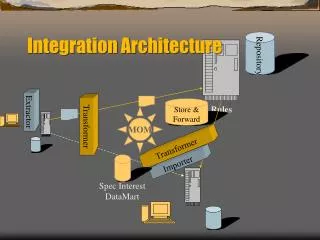
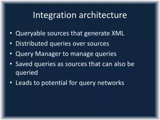
This workshop discusses the integration of motion control, chopper, and sample environment systems into instrument architecture, including time stamping methods and connections to EPICS for enhanced control and monitoring.

E N D
Integration of Motion Control, Chopper and Sample Environment into Instrument Architecture Thomas Gahl (EEG) Workshop on Instrument Architecture, 2013-06-14
Three Assumptions first • Devices are local systems with locally closed control loops (due to speed and precision of the control process) and locally handled alarm/interlock features • Devices will connect to EPICS: Receiving commands from and sending status information (metadata) to EPICS • All metadata have to be read out regularly and time stamped with the absolute facility time Workshop on Instrument Architecture, 2013-06-14
Time stamping • On the control of local devices 4 different types of time stamping are possible according to the latency requirements • T1: read out metadata through TCP/IP or RS232, time stamped in the control box (latency few hundreds of msec) • T2: Synchronizing the periodical reading of metadata in the controller with a pulse from the timing system (latency few msec) • T3: Importing absolute time to Controller and time stamping there (latency well below 1 msec) • T4: Direct reading of metadata (from sensor) into the control box and time stamping there (latency well below 1 msec) Workshop on Instrument Architecture, 2013-06-14
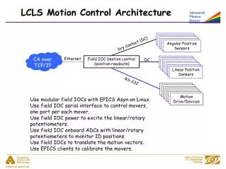
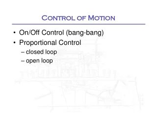
Motion Control • Motion Control Unit is connected to the Control box through TCP/IP for commands and readings • On motion control all 4 different types of time stamping might be applicable to fulfill the latency requirements derived from the required precision and the used speed • Read out of positions through TCP/IP, time stamped T1 in the control box • Synchronizing a periodically reading of positions with a pulse from the timing system, time stamping T2 • Importing absolute time to Motion Control Unit with time stamping T3 • Direct reading of encoder position into the control box with time stamping T4 Workshop on Instrument Architecture, 2013-06-14
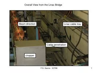
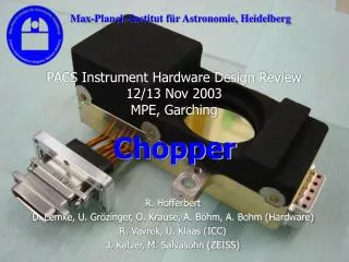
Chopper • Chopper control includes set and read of speed and phase via TCP/IP or RS232 and synchronizing to the pulse of the source (time stamping T1) • There might be analog signals to read to analyse the status of the magnetic bearings control (time stamping T4 in the control box) • Sensors including vacuum and cooling may be also red in directly into EPICS (time stamping T4) Workshop on Instrument Architecture, 2013-06-14
Sample Environment • Digital and (fast) analog signals can be connected directly to cards in the control box (time stamping T4) • Processes in SE are in most cases slow, so controllers are connected to EPICS via TCP/IP or RS232 and metadata is time stamped in the control box (T1) • There might be a direct reading of the sensors into EPICS as well (time stamping T4) Workshop on Instrument Architecture, 2013-06-14