8/16 x E1/T1 over Ethernet Multiplexer (TDMoIP) Product Presentation
V aliant C ommunications L imited. Telecom Transmission Solutions. 8/16 x E1/T1 over Ethernet Multiplexer (TDMoIP) Product Presentation. Updated: 29 April, 2010. Product Overview.

8/16 x E1/T1 over Ethernet Multiplexer (TDMoIP) Product Presentation
E N D
Presentation Transcript
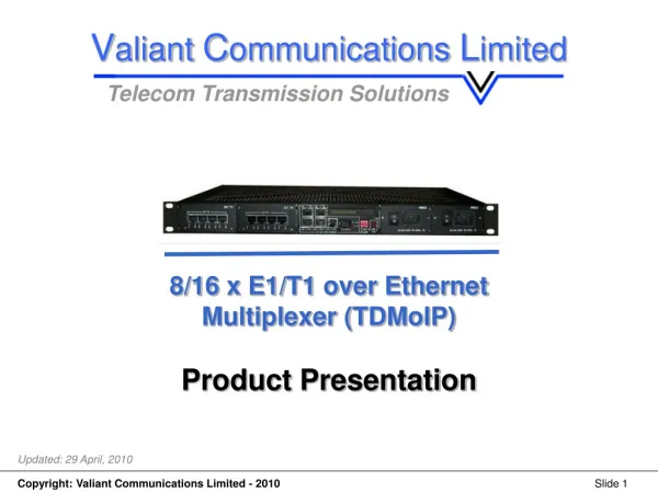
Valiant Communications Limited Telecom Transmission Solutions 8/16 x E1/T1 over Ethernet Multiplexer (TDMoIP) Product Presentation Updated: 29 April, 2010
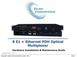
Product Overview • VCL-8/16 x E1/T1 over Ethernet (TDMoIP) unit provides the user with E1/T1 over Ethernet (IP) conversion and allows the user to transport upto 16 E1/T1 channels (carrying data or voice) over Ethernet (IP) Network • Support SNMP V2 monitoring and traps • VCL-8/16 x E1/T1 over Ethernet multiplexer (TDMoIP) product supports upto 8 or 16 E1s/T1s (user selectable) and 5 Gigabit electrical ports and 1 Gigabit (GE) optical port • It is an E1/T1 extension device which utilizes the Ethernet / IP Network to transport E1 or a T1 signal in real-time • Useful for the Real-time applications carrying VOICE, VIDEO and DATA • Compatible with 1 and 2 port TDMoIP versions • The uplink ports and user data ports are IEEE 802.3 compliant, 10/100/ 1000M auto-negotiating Ethernet ports.
Product Overview • The QoS features include short and stable transmission delay, low jitter and wander. • Support 802.1Q based VLAN tagging and 802.1p QoS functions • VLAN settings for E1 services with 802.1Q and QinQ mode • Supports 120 Ohms balanced and 75 Ohms unbalanced (optional) E1 ports • Suitable for achieving higher bandwidth utilization • It converts the E1/T1 frame format into Ethernet Data for transmission over the Ethernet or IP Network and then re-converts the Ethernet data back into E1/T1 frame format at the far-end terminal, to inter-connect two or more E1/T1 devices over the Ethernet / IP Network • Support 1+1 AC and / or DC redundant power supply options • Compact and low cost.
How it works • The equipment is a TDM / Packet processing unit. • It converts E1/T1 data stream into Ethernet packets with or without IP headers. • These packets are transported over the Ethernet network. • At the far-end the packets from the uplink Ethernet port are sorted and processed to re-assemble into the original E1 or T1 data stream. • It also uses algorithms to recover the E1 or T1 clock synchronization and to ensure that the reconstructed clock will meet the stringent requirement of TDM applications.
Features and Highlights • Up to 16 E1/T1 Ports supported • Provides 5 Gigabit (GE) electrical ports and 1 Gigabit (GE) optical port. All 6 Gigabit (GE) ports serve as network uplinks or users ports and any of the 5 Gigabit (GE) electrical ports may act as Management Port • E1/T1 signal is a TDM signal which transmits information in a constant bit rate of E1@ 2048Kbps, T1@ 1544Kbps • User-friendly Web server supported for easy setup and maintenance • Supports SNMP V1/V2 network management • Ethernet built-in layer 2 switch, supports VLAN, complies with IEEE 802.3x, 802.1P • Provide two removable E1 cards (add/remove), each card supports 8 E1/T1s • Point-to-point and point-to-multipoint applications supported.
Features and Highlights • PCM frame synchronization protection • User definable encapsulation packet size for different applications • Support Ethernet encapsulation and UDP/IP protocol encapsulation • Support VLAN settings for E1 service and in-band VLAN management • Jitter buffer for packet delay variation (PDV) • Local Ethernet port throughput limit assuring E1 QoS • 120Ω balanced E1/T1 port, RJ-45 connector • Supports 75Ω unbalanced port (optional) • Stable E1 clock recovery, low jitter and wander • Low processing delay for E1 channels, high bandwidth usage efficiency • Local and remote E1/T1 LOS and AIS and packet loss indication for trouble-shooting and maintenance.
Features and Highlights • Supports 1+1 redundant power supply which can be configure various combinations (AC, DC, AC+AC, AC+DC and DC+DC) • AC power supply range 110V ~ 240V AC • DC power supply range 36V ~ 72V DC.
Application • The equipment may be used for the following purposes: • Connecting point-to-point E1 / T1 devices over Ethernet or IP network • Establishing point-to-point E1 / T1 link over wireless bridge (Ethernet Radios) • Connecting point-to-multipoint E1 / T1 devices over Ethernet or IP network with 1 and 2 port TDMoIP version • Establishing point-to-multipoint E1 / T1 link over wireless bridge (Ethernet Radios) 1 and 2 port TDMoIP version.
Application Diagram Point to point applications Uplink Uplink IP Networks Up to 16 E1/T1 links Up to 16 E1/T1 links 8/16 Port TDMoIP 8/16 Port TDMoIP Uplink Uplink Radio Link Up to 16 E1/T1 links Up to 16 E1/T1 links 8/16 Port TDMoIP 8/16 Port TDMoIP Note: When connecting to a wireless LAN bridge (Ethernet Radio), care must be taken to protect the equipment from lightening strikes and surges by installing surge protection devices with a good earth / ground connection. Poor earth / ground connections may also degrade the operation of the Ethernet port, causing severe packet losses.
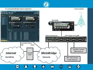
E1 / T1 Multiplexer E1 / T1 Multiplexer E1 / T1 Multiplexer E1/T1 PBX E1/T1 PBX 1 Port TDMoIP 1 Port TDMoIP 1 Port TDMoIP 1 Port TDMoIP 2 Port TDMoIP Central Site 8/16 Port TDMoIP E1/T1 PBX E1/T1 PBX E1 / T1 Multiplexer E1 / T1 Multiplexer E1 / T1 Multiplexer Application Diagram Point to multi-point application# 1 Remote Site - 1 Remote Site - 2 Remote Site - 3 Remote Site - 4 Remote Site - 5 Cell Tower E1 / T1 E1 / T1 E1 / T1 E1 / T1 Uplinks Uplinks IP Network Uplink
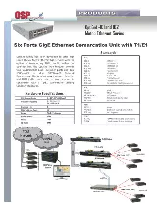
E1 / T1 Multiplexer E1/T1 PBX E1/T1 PBX 1 Port TDMoIP 1 Port TDMoIP 1 Port TDMoIP 2 Port TDMoIP 2 Port TDMoIP E1 / T1 Multiplexer IP Network E1 / T1 Multiplexer E1/T1 PBX Application Diagram Point to multi-point application# 2 Remote Site - 1 Remote Site - 4 Remote Site - 5 Radio Link Cell Tower E1 / T1 Uplinks Uplinks Remote Site - 2 Radio Link Uplink Central Site Uplinks Remote Site - 3 Radio Link 8/16 Port TDMoIP E1/T1 PBX E1/T1 PBX E1/T1 PBX E1 / T1 Multiplexer E1 / T1 Multiplexer E1 / T1 Multiplexer
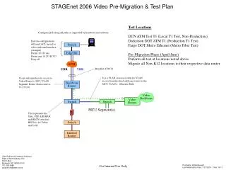
Web Management (Through Web Browser) • Monitoring and Managing the equipment through the Web Management using Web Browser (Internet Explorer, Fire Fox etc)
Web Management (Through Web Browser) • Monitoring and Managing the equipment through the Web Management using Web Browser (Internet Explorer, Fire Fox etc)
Thank you for your attention For more details visit us at our Website at http://www.valiantcom.com U.K. Valiant Communications (UK) Ltd 1, Acton Hill Mews, 310-328 Uxbridge Road, London W3 9QN, United Kingdom E-mail: gb@valiantcom.com Website: http://www.valiantcom.com INDIA Valiant Communications Limited71/1, Shivaji Marg, New Delhi - 110015, India E-mail: mail@valiantcom.com Website: http://www.valiantcom.com U.S.A. Valcomm Technologies Inc. 4000 Ponce de Leon, Suite 470Coral Gables, FL 33146United States of America E-mail: us@valiantcom.com Website: http://www.valiantcom.com