Multiplexer and DeMultiplexer
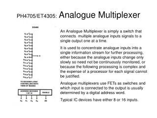
Multiplexer and DeMultiplexer. Multiplexer (Data Selectors). The Term ‘Multiplex’ means “many into one”. Multiplexing is the process of transmitting a large number of information over a single line. Cont.,.

Multiplexer and DeMultiplexer
E N D
Presentation Transcript
Multiplexer (Data Selectors) • The Term ‘Multiplex’ means “many into one”. • Multiplexing is the process of transmitting a large number of information over a single line.
Cont., • A digital multiplexer (MUX) is a combinational circuit that selects one digital information several sources and transmits the selected information on a single output line.
Cont., • A multiplexer is also called a data sector • The multiplexer has several data-input lines and a single output line.
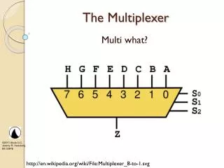
4 to 1 Multiplexer Logic Symbol S1 Select inputs S0 Y 4-to-1 MUX D0 D1 Data inputs Data output D2 D3
Cont., • To demonstrate the operation of the circuit, consider the case when S1 S0 =00. • If S1 S0 =00 is applied to the select lines, the AND gate associated with D0 will have two of its input equal to 1 and the third input connected to D0. • The other three AND gates have 0 in at least one of their inputs, which make their output equal to 0. • Hence, the OR output (Y) is equal to the value of D0.
Cont., • Thus, it provides a path from the selected input and the data on the input D0 appears on the data-output line (Y). • If S1 S0 =01 (binary 1) applied to the select lines , the data on the input D1 appears on the data output line.
Cont., • If S1 S0 =10 (binary 2) is applied, the data on the input D2 appears on the output line (Y). • Similarly, if S1 S0 =11 is applied, the data on D3 is switched to the output line (Y). • The AND gates and the inverters resemble a decoder circuit, and indeed they decode the input select lines. • In general, a 2n–to-1 multiplexer is constructed from n-to -2n decoder by adding to it 2n input lines, one each AND gate.
Cont., • The output of the AND gates are applied to a single OR gate to provide a single output. • The size of the multiplexer is specified by the number 2n of input lines and the single output line. • Multiplexer ICs have an enable input to control the operation of the unit. • The enable input (also called strobe) can be used to cascade two or more multiplexer ICs to construct a multiplexer with larger number of inputs
DeMultiplexer (Data Distributors) • The word “Demultiplex” means “One into many”. • DeMultiplexing is the process of taking information from one input and transmitting the same over one of several outputs.
Block diagram of DeMultiplexer Output 0 Output 1 Input Output 2 Output 3 S1 S0 (Select pins)
1 to 4 DeMultiplexer Logic Symbol S1 Y0 Select inputs S0 Y1 1-to4 DMUX Y2 Data input D Y3 Data outputs
Cont., • A 1-to-4 DeMultiplexer has a single input (D), four outputs (Y0 to Y3) and two select inputs (S0 and S1).
Cont., • From the truth table, it is clear that the data input is connected to output Y0 when S1=0 and S0=0 and the data input is connected to output Y1 when S1=0 and S0=1. • Similarly, the data input is connected to outputs Y2 and Y3 when S1=1 and S0=0 and when S1=1 and S0=1 respectively.
Expressions of output Y0 = S1 S0 D Y1 = S1 S0 D Y1 = S1 S0 D Y1 = S1 S0 D
Cont., • Now, using the above expressions, a 1-to-4 DeMultiplexer can be implemented using four 3- input AND gates and two NOT gates. • Here, the input data line is connected to all the AND gates
Cont., • The two select lines S1 and S0 enable only one at a time and the data that appears on the input line passes through the selected gate to the associated output line.
The End ….. Thank you ….. M.S.P.V.L. Polytechnic college, Pavoorchatram.