Download
1 / 19
190 likes | 295 Vues
This document proposes using Finite Geometry LDPC code for internet data transport due to its simplicity, efficiency, and error correction advantages. The encoding and decoding algorithms are straightforward, making it suitable for high-volume data transport. The LDPC code can be easily applied in erasure channels, enhancing data reliability. By utilizing the specific properties of Finite Geometry, such as block lengths and code rates, the encoding and decoding complexity grows linearly with code length. Additionally, the Parity Check Matrix can be optimized for cyclic form, reducing memory usage. The document explains the encoding and decoding procedures in the erasure channel, emphasizing the efficient transmission and error correction processes. Through detailed steps and examples, the advantages and implementation of Finite Geometry LDPC code in internet data transport are highlighted.

E N D
Application of Finite Geometry LDPC code on the Internet Data Transport Wu Yuchun Oct 2006 Huawei Hisi Company Ltd
Contents • Abstract. • Simple Encoding Algorithm • Simple Decoding Algorithm • Other Advantages • Applied in the Erasure Channel • End
Abstract • In this file we propose a Finite Geometry LDPC(FG_LDPC) code to be applied in the Internet data transport because of several of its advantages which we think are very important for the huge amount of data transport.
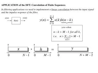
Simple Encoding Algorithm The Encoding of FG_LDPC code is very simple. It’s just like the Encoding of a cyclic code. Suppose we denote Message Polynomial Generator Polynomial Then the output of the Encoder is just
Simple Decoding Algorithm. (1/4) Some of FG_LDPC Codes are One Step Majority Logical Decodable Codes, so the decoding algorithm is very simple if compared to other LDPC decoding algorithms such as Sum Product Algorithm, Bit Flip Algorithm…. The decoding procedure can be summarized as follows: 1)
Simple Decoding Algorithm(2/4) Where is the received vector (one row of the Received Matrix as explained in Slide11-13) and H is the Parity Check Matrix of FG_LDPC Code. We call as Syndrome Vector. 2) Calculate the Error Vector For every element , we define a position set A(i), which consists the row indexs of H that the ith element of that row is “1”. then if more than half of s(A(i)) are 1, we decided that , i.e, the ith received element is in error, otherwise, the ith received element is correct and
Simple Decoding Algorithm(3/4) • For Example, for the Euclidean Finite Geometry The corresponding Parity Check Matrix is
Simple Decoding Algorithm(4/4) • For and , from H we can see that the • So if more than half of the Syndrome element of is “1”, , otherwise, • If more than half of the Syndrome element of is “1”, , otherwise,
Other Advantages (1/2) • There is an ample selection of block lengths and code rates of FG_LDPC Code; • Along with the increase of Code Length, the Encoding and Decoding Complexity only increase linearly
Other Advantages (2/2) • For some specific Finite Geometry, the Parity Check Matrix H can be put in a cyclic form, any row of the H is only a cyclic shifted version of the first row. So in the real application, we only need to save one row of H rather than the whole Matrix H. • In real application, we can calculate the g(x) and H off line and save it, then just use it when the transport begin. This will further reduce the CPU load on the transport procedure;
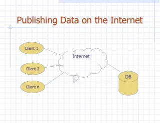
Applied in the Erasure Channel(1/7) The application of this FG_LDPC in the Erasure Channel is illustrated in the following figure:
Applied in the Erasure Channel(2/7) • In the sender side: • Step1: Write all data of a block into a Source Matrix column by column. Each Source Symbol correspond to a column of the Source Matrix, Each Source Vector correspond to a row of the Source Matrix; • Step2: Encoding was done on the Source Matrix row by row. Each Source Vector(k bits) was encoded into a Encoding Vector(n bits). after encoding, we obtain the Encoding Matrix with dimension of ((E*8) * n); • Step3: Each column of the Encoding Matrix was considered as an encoding symbol, transmit the Encoding Matrix column by column.
Applied in the Erasure Channel(3/7) • In the receiver side: • Step1: Arrange all received symbols of a block into a Receive Matrix. Each received symbol correspond to a column of the Receive Matrix. • Step2: Decode the Receive Matrix row by row, and obtain the Decoded Matrix with dimension of ((E*8) * k) ; • Step3: Output the Decoded Matrix column by column.
Applied in the Erasure Channel(4/7) • To be simple, for the transmission, the data is transmitted symbol by symbol (or column by column); for encoding and decoding, the data is in a vector by vector (or row by row) order. • For each encoding and decoding operation, it’s just the operation as described in Slide 4 and Slide 5-8. • We can see that each Erasured symbol only contribute one Erasured bit for the decoding unit. because the data fed into the decoder is a row vector. So it’s just like the interleaver: disturb the burst erasure (Erasured Symbol) into a lot of Bit Erasures.
Applied in the Erasure Channel(5/7) • Another Encoding method to apply FG_LDPC in Erasure Channel are as follow figure:
Applied in the Erasure Channel(6/7) • The Encoding Procedure is: • Step1: All the registers are set to 0; • Step2: Key K0 connect to point A00 and K1 connect to point A01, and the source symbols are input in the order of U0 ,U1,U2, …Uk-1, • Step3: After k clock cycles, all k Source Symbols was finished, we connect Key K0 to point A01 and K1 to point A11, after another n-k clock cycles, all n-k parity symbols was outputed. • Then the encoding was finished, the Output symbols are U0, U1, U2, …Uk-1, P0, P1, P2, …Pn-k-1. Each symbol is E Bytes wide.
Applied in the Erasure Channel(7/7) • Another Decoding Algorithm of FG_LDPC in Erasure Channel can be found in Chapter 6.4 of 《draft-ietf-rmt-bb-fec-ldpc-03》: • For every Erasure Symbol, searching on all related check equations, if there is an equation in which only this Erasure Symbol is a variable, then we can recover this Erasure Symbol; • Replacing these Recovered Erasure Symbols in all check equations, and continue to Recover remained Erasure Symbols in the same way iteratively, • If in some step, For any one of the remained Erasure Symbols, we can’t find a check equation in which only this Erasure Symbol is a variable, we finished decoding and report that this block of symbols was failed to be recovered, otherwise, we can recover this block of symbols successfully.
End • Any comments and questions are welcomed and appreciated. We hope to work together with people who are interest in it so that we can improve and perfect this FEC scheme on the Internet data transport.