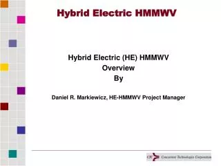
Engine Speed Control for HMMWV
Engine Speed Control for HMMWV. Members. Faculty Advisor Industrial Advisor Dr. Marshall Molen Mr. Dan Harkins Picture Unavailable Team Members Team Leader


Engine Speed Control for HMMWV
E N D
Presentation Transcript
Members • Faculty AdvisorIndustrial Advisor Dr. Marshall MolenMr.Dan HarkinsPicture Unavailable • Team Members Team Leader Daniel Kennedy Patrick McNally Catalina Olarte Jarrod Fortinberry Overcurrent Protection Stepper Motor Research Website Design Research Signal Processing Power Electronics Simulations Microcontroller Interface
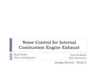
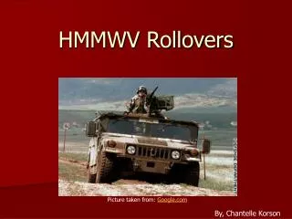
Overview • United States Army wants to deploy high-power mobile radar equipment in remote areas • Integrating these systems into HMMWVs would allow remote deployment Problem • The change in electrical load requires a change in speed • HMMWV is unable to supply required power at idle speeds Effects • Load does not receive required power • Increased wear and tear on the engine
SDII Focus • Lower power (cost) DC to DC converter • Improve driver circuit • Simulation • Design packaging • Improve stability at higher RPMs through use of a longer lever arm
Cheaper DC/DC Converter Stepper Motor New Design Old Design Electromagnet 28V From Battery 12V DC/DC Converter 5V +/- 15V Electronics Current Transducer Smaller and cheaper converter reduces component costs by $58.40
Current Chopper Stepper Motor Chopper Circuit New Design Electromagnet 28V From Battery 5V DC/DC Converter +/- 15V Electronics Current Transducer Reduces the size of the circuit. Reduces heat generation and power consumption of stepper motor and driver circuit.
Simulation • Previous schematic functioned based on discrete data points collected through experimentation • New schematic uses more advanced models taken from the SimPower toolbox to model the electrical system
Packaging • Packaging requirements: • Withstand extreme environmental conditions • Solution: • Pre-manufactured, NEMA4 rated, aluminum enclosure
NEMA Standards • National Electrical Manufacturers Association standards publication No 250 • NEMA 4 : • Indoor/outdoor use • Protection for operators against incidental contact • Protection from: • Falling dirt • Rain • Sleet • Snow • Windblown dust • Splashing and hose directed water • External formation of ice will not damage unit
Old Throttle Attachment Pivot point • Too close to the pivot point • At high RPMs the resolution of the stepper motor is inadequate Throttle attachment
New Throttle Attachment New attachment • Longer lever arm: • Increases accuracy • Decreases stabilization times • Increases torque Old attachment Pivot point
Design Constraint - +/- 1% Controller stabalizes within +/- 50 rpms over the entire range. Design constraint – +/- 5% Controller Accuracy
Cost Summary Design constraint: Cost of Parts < $600
Acknowledgement s • Dr. Marshall Molen • Evan Burnett • Bill Buchanon • Josh Lofton • Angela Card • Robin Kelley • Dan Harkins • Dr. Picone