Understanding the graphics pipeline
Understanding the graphics pipeline. Lecture 2. Lecture Outline. A historical perspective on the graphics pipeline Dimensions of innovation. Where we are today Fixed-function vs programmable pipelines A closer look at the fixed function pipeline Walk thru the sequence of operations

Understanding the graphics pipeline
E N D
Presentation Transcript
Understanding the graphics pipeline Lecture 2 http://www.cis.upenn.edu/~suvenkat/700/
Lecture Outline • A historical perspective on the graphics pipeline • Dimensions of innovation. • Where we are today • Fixed-function vs programmable pipelines • A closer look at the fixed function pipeline • Walk thru the sequence of operations • Reinterpret these as stream operations • We can program the fixed-function pipeline ! • Some examples • What constitutes data and memory, and how access affects program design. http://www.cis.upenn.edu/~suvenkat/700/
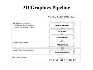
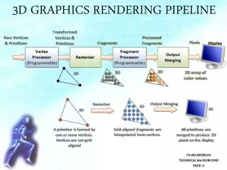
The evolution of the pipeline • Elements of the graphics pipeline: • A scene description: vertices, triangles, colors, lighting • Transformations that map the scene to a camera viewpoint • “Effects”: texturing, shadow mapping, lighting calculations • Rasterizing: converting geometry into pixels • Pixel processing: depth tests, stencil tests, and other per-pixel operations. • Parameters controlling design of the pipeline: • Where is the boundary between CPU and GPU ? • What transfer method is used ? • What resources are provided at each step ? • What units can access which GPU memory elements ? http://www.cis.upenn.edu/~suvenkat/700/
Rasterization and Interpolation Raster Operations Generation I: 3dfx Voodoo (1996) • One of the first true 3D game cards • Worked by supplementing standard 2D video card. • Did not do vertex transformations: these were done in the CPU • Did do texture mapping, z-buffering. http://accelenation.com/?ac.id.123.2 Vertex Transforms Primitive Assembly Frame Buffer CPU GPU PCI http://www.cis.upenn.edu/~suvenkat/700/
Rasterization and Interpolation Raster Operations Generation II: GeForce/Radeon 7500 (1998) • Main innovation: shifting the transformation and lighting calculations to the GPU • Allowed multi-texturing: giving bump maps, light maps, and others.. • Faster AGP bus instead of PCI http://accelenation.com/?ac.id.123.5 Vertex Transforms Primitive Assembly Frame Buffer GPU AGP http://www.cis.upenn.edu/~suvenkat/700/
Rasterization and Interpolation Raster Operations Generation III: GeForce3/Radeon 8500(2001) • For the first time, allowed limited amount of programmability in the vertex pipeline • Also allowed volume texturing and multi-sampling (for antialiasing) http://accelenation.com/?ac.id.123.7 Vertex Transforms Primitive Assembly Frame Buffer GPU AGP Small vertex shaders http://www.cis.upenn.edu/~suvenkat/700/
Rasterization and Interpolation Raster Operations Generation IV: Radeon 9700/GeForce FX (2002) • This generation is the first generation of fully-programmable graphics cards • Different versions have different resource limits on fragment/vertex programs http://accelenation.com/?ac.id.123.8 Vertex Transforms Primitive Assembly Frame Buffer AGP Programmable Vertex shader Programmable Fragment Processor http://www.cis.upenn.edu/~suvenkat/700/
Generation IV.V: GeForce6/X800 (2004) Not exactly a quantum leap, but… • Simultaneous rendering to multiple buffers • True conditionals and loops • Higher precision throughput in the pipeline (64 bits end-to-end, compared to 32 bits earlier.) • PCIe bus • More memory/program length/texture accesses http://www.cis.upenn.edu/~suvenkat/700/
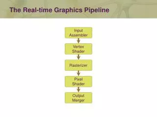
Rasterization and Interpolation Raster Operations Fixed-function pipeline 3D API Commands 3D API: OpenGL or Direct3D 3D Application Or Game CPU-GPU Boundary (AGP/PCIe) GPU Command & Data Stream Vertex Index Stream Pixel Location Stream Assembled Primitives Pixel Updates GPU Front End Primitive Assembly Frame Buffer Transformed Vertices Transformed Fragments Pre-transformed Vertices Pre-transformed Fragments Programmable Fragment Processor Programmable Vertex Processor http://www.cis.upenn.edu/~suvenkat/700/
A closer look at the fixed-function pipeline http://www.cis.upenn.edu/~suvenkat/700/
Pipeline Input Vertex Image F(x,y) = (r,g,b,a) (x, y, z) (r, g, b,a) (Nx,Ny,Nz) (tx, ty,[tz]) (tx, ty) (tx, ty) Material properties* http://www.cis.upenn.edu/~suvenkat/700/
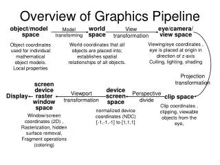
ModelView Transformation • Vertices mapped from object space to world space • M = model transformation (scene) • V = view transformation (camera) Each matrix transform is applied to each vertex in the input stream. Think of this as a kernel operator. X Y Z 1 X’ Y’ Z’ W’ M * V * http://www.cis.upenn.edu/~suvenkat/700/
Lighting Lighting information is combined with normals and other parameters at each vertex in order to create new colors. Color(v) = emissive + ambient + diffuse + specular Each term in the right hand side is a function of the vertex color, position, normal and material properties. http://www.cis.upenn.edu/~suvenkat/700/
Clipping/Projection/Viewport(3D) • More matrix transformations that operate on a vertex to transform it into the viewport space. • Note that a vertex may be eliminated from the input stream (if it is clipped). • The viewport is two-dimensional: however, vertex z-value is retained for depth testing. Clip test is first example of a conditional in the pipeline. However, it is not a fully general conditional. Why ? http://www.cis.upenn.edu/~suvenkat/700/
Rasterizing+Interpolation • All primitives are now converted to fragments. • Data type change ! Vertices to fragments Fragment attributes: (r,g,b,a) (x,y,z,w) (tx,ty), … Texture coordinates are interpolated from texture coordinates of vertices. This gives us a linear interpolation operator for free. VERY USEFUL ! F(x, y) = (lo * x + range, lo’ * y + range’) http://www.cis.upenn.edu/~suvenkat/700/
Per-fragment operations • The rasterizer produces a stream of fragments. • Each fragment undergoes a series of tests with increasing complexity. Test 1: Scissor If (fragment lies in fixed rectangle) let it pass else discard it Test 2: Alpha If( fragment.a >= <constant> ) let it pass else discard it. Scissor test is analogous to clipping operation in fragment space instead of vertex space. Alpha test is very useful for implementing shadow maps. It is a slightly more general conditional. Why ? http://www.cis.upenn.edu/~suvenkat/700/
Per-fragment operations • Stencil test: S(x, y) is stencil buffer value for fragment with coordinates (x,y) • If f(S(x,y)), let pixel pass else kill it. Update S(x, y) conditionally depending on f(S(x,y)) and g(D(x,y)). • Depth test: D(x, y) is depth buffer value. • If g(D(x,y)) let pixel pass else kill it. Update D(x,y) conditionally. http://www.cis.upenn.edu/~suvenkat/700/
Per-fragment operations • Stencil and depth tests are more general conditionals. Why ? • These are the only tests that can change the state of internal storage (stencil buffer, depth buffer). This is very important. • One of the update operations for the stencil buffer is a “count” operation. Remember this! • Unfortunately, stencil and depth buffers have lower precision (8, 24 bits resp.) http://www.cis.upenn.edu/~suvenkat/700/
Post-processing • Blending: pixels are accumulated into final framebuffer storage new-val = old-val op pixel-value If op is +, we can sum all the (say) red components of pixels that pass all tests. Problem: In generation<= IV, blending can only be done in 8-bit channels (the channels sent to the video card); precision is limited. We could use accumulation buffers, but they are very slow. http://www.cis.upenn.edu/~suvenkat/700/
Readback = Feedback What is the output of a “computation” ? • Display on screen. • Render to buffer and retrieve values (readback) Readbacks are VERY slow ! • What options do we have ? • Render to off-screen buffers like accumulation buffer • Copy from framebuffer to texture memory ? • Render directly to a texture ? • Stay tuned… PCI and AGP buses are asymmetric: DMA enables fast transfer TO graphics card. Reverse transfer has traditionally not been required, and is much slower. This motivates idea of “pass” being an atomic “unit cost” operation. http://www.cis.upenn.edu/~suvenkat/700/
Time for a puzzle… http://www.cis.upenn.edu/~suvenkat/700/
An Example: Voronoi Diagrams. http://www.cis.upenn.edu/~suvenkat/700/
Definition • You are given n sites (p1, p2, p3, … pn) in the plane (think of each site as having a color) • For any point p in the plane, it is closest to some site pj. Color p with color i. • Compute this colored map on the plane. In other words, Compute the nearest-neighbour diagram of the sites. http://www.cis.upenn.edu/~suvenkat/700/
Example http://www.cis.upenn.edu/~suvenkat/700/
Hint: Think in one dimension higher The lower envelope of “cones” centered at the points is the Voronoi diagram of this set of points. http://www.cis.upenn.edu/~suvenkat/700/
The Procedure • In order to compute the lower envelope, we need to determine, at each pixel, the fragment having the smallest depth value. • This can be done with a simple depth test. • Allow a fragment to pass only if it is smaller than the current depth buffer value, and update the buffer accordingly. • The fragment that survives has the correct color. http://www.cis.upenn.edu/~suvenkat/700/
Let’s make this more complicated • The 1-median of a set of sites is a point q* that minimizes the sum of distances from all sites to itself. q* = arg min Σ d(p, q) WRONG ! RIGHT ! http://www.cis.upenn.edu/~suvenkat/700/
A First Step Can we compute, for each pixel q, the value F(q) = Σ d(p, q) We can use the cone trick from before, and instead of computing the minimum depth value, compute the sum of all depth values using blending. What’s the catch ? http://www.cis.upenn.edu/~suvenkat/700/
We can’t blend depth values ! • Using texture interpolation helps here. • Instead of drawing a single cone, we draw a shaded cone, with an appropriately constructed texture map. • Then, fragment having depth z has color component 1.0 * z. • Now we can blend the colors. • OpenGL has an aggregation operator that will return the overall min Warning: we are ignoring issues of precision. http://www.cis.upenn.edu/~suvenkat/700/
Now we apply a streaming perspective… http://www.cis.upenn.edu/~suvenkat/700/
Stream data (data associated with vertices and fragments) Color/position/texture coordinates. Functionally similar to member variables in a C++ object. Can be used for limited message passing: I modify an object state and send it to you. This is how hardware shadow mapping can be done (using the alpha-channel) “Persistent” data (associated with buffers). Depth, stencil, textures. Can be modifed by multiple fragments in a single pass. Functionally similar to a global array BUT each fragment only gets one location to change. Can be used to communicate across passes. Two kinds of data http://www.cis.upenn.edu/~suvenkat/700/
Who has access ? • Memory “connectivity” in the GPU is tricky. • In a traditional C program, all global variables can be written by all routines. • In the fixed-function pipeline, certain data is private. • A fragment cannot change a depth or stencil value of a location different from its own. • The framebuffer can be copied to a texture; a depth buffer cannot be copied in this way, and neither can a stencil buffer. • Only a stencil buffer can count (efficiently) • In the fixed-function pipeline, depth and stencil buffers can be used in a multi-pass computation only via readbacks. • A texture cannot be written directly. • In programmable GPUs, the memory connectivity becomes more open, but there are still constraints. Understanding access constraints and memory “connectivity” is a key step in programming the GPU. http://www.cis.upenn.edu/~suvenkat/700/
How does this relate to stream programs ? • The most important question to ask when programming the GPU is: What can I do in one pass ? • Limitations on memory connectivity mean that a step in a computation may often have to be deferred to a new pass. • For example, when computing the second smallest element, we could not store the current minimum in read/write memory. • Thus, the “communication” of this value has to happen across a pass. http://www.cis.upenn.edu/~suvenkat/700/
Next Lecture: 01/18/05 • We will examine the programmable pipeline of modern graphics hardware (GeForceFX/GeForce6). A point to ponder: If we wished to compute the kth smallest element of a set of numbers, how many passes do we need ? Can you come up with a plausible reason why you can’t do any better ? http://www.cis.upenn.edu/~suvenkat/700/
Administrivia • Most of you have filled out the survey: if you haven’t, please do so soon ! • If you don’t have access to HMS and do not have alternate access to an FX or better graphics card, send me email. • If you wish to buy nVidia cards at cost, email Matt Beitler (beitler@cis.upenn.edu) soon. • If you wish to discuss project ideas, email me and we can set a time: it’s never too soon to start thinking ! • There is now a discussion forum on Blackboard for Cg/GPU questions. Post questions there; Paul and I will monitor the forum. http://www.cis.upenn.edu/~suvenkat/700/