Chapter 16 CMOS Amplifiers
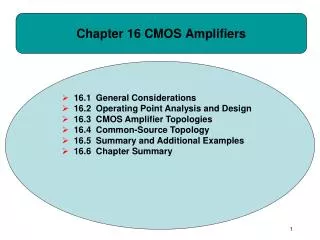
Chapter 16 CMOS Amplifiers. 16.1 General Considerations 16.2 Operating Point Analysis and Design 16.3 CMOS Amplifier Topologies 16.4 Common-Source Topology 16.5 Summary and Additional Examples 16.6 Chapter Summary. Chapter Outline. Example: Desired I/O Impedances.

Chapter 16 CMOS Amplifiers
E N D
Presentation Transcript
Chapter 16 CMOS Amplifiers • 16.1 General Considerations • 16.2 Operating Point Analysis and Design • 16.3 CMOS Amplifier Topologies • 16.4 Common-Source Topology • 16.5 Summary and Additional Examples • 16.6 Chapter Summary
Chapter Outline CH 16 CMOS Amplifiers
Example: Desired I/O Impedances CH 16 CMOS Amplifiers
Method to Measure the I/O Impedances • To measure Rin(Rout), deactivate all the other independent sources in the circuit and find the ratio of vX/iX. CH 16 CMOS Amplifiers 4
Example: Input Impedance of a Simple Amplifier CH 16 CMOS Amplifiers 5
The Concept of Impedance at a Node • When the other node of a port is grounded, it is more convenient to use the concept of impedance at a node. CH 16 CMOS Amplifiers 6
Example: Impedance Seen at Drain CH 16 CMOS Amplifiers 7
Example: Impedance Seen at Source CH 16 CMOS Amplifiers 8
Impedance Summary • Looking into the gate, we see infinity. • Looking into the drain, we see rO if the source is (ac) grounded. • Looking into the source, we see 1/gm if the gate is (ac) grounded and rO is neglected. CH 16 CMOS Amplifiers 9
Bias and Signal Levels for a MOS Transistor • Bias point analysis establishes the region of operation and the small-signal parameters. • On top of the bias point, small signals are applied to the circuit. CH 16 CMOS Amplifiers 10
General Steps in Circuit Analysis • First, the effects of constant voltage/current sources are analyzed when signal sources are deactivated. • Second, small-signal analysis is done when constant sources are set to zero. CH 16 CMOS Amplifiers 11
Simplification of Supply Voltage Notation CH 16 CMOS Amplifiers 12
Example: Amplifier Driven by a Microphone • Since the DC (average) value is at zero, and 20mV is not sufficient to turn on M1, M1 is off and Vout is at VDD. CH 16 CMOS Amplifiers 13
Example: Amplifier with Gate Tied to VDD • Since the gate voltage level is fixed at VDD, no signal current will be produced my M1, leading to no amplification. CH 16 CMOS Amplifiers 14
Example: Amplifier with Gate Bias • With proper value of VB, M1 can operate in the desired saturation region and amplify the incoming voice signal. CH 16 CMOS Amplifiers 15
Simple Biasing • In (a), VGS=VDD, whereas in (b) VGS equals to a fraction of VDD. CH 16 CMOS Amplifiers 16
Example: Bias Current and Maximum RD CH 16 CMOS Amplifiers 17
Capacitive Coupling • Capacitive coupling is used to block the zero DC output value of the microphone and pass the voice signal to the amplifier. CH 16 CMOS Amplifiers 18
Biasing with Source Degeneration CH 16 CMOS Amplifiers 19
Example: ID and Maximum RD for Source Degeneration Biasing CH 16 CMOS Amplifiers 20
Example: Maximum W/L and Minimum RS CH 16 CMOS Amplifiers 21
Self-Biased MOS Stage • The gate voltage is provided by the drain with no voltage drop across RG and M1 is always in saturation. CH 16 CMOS Amplifiers 22
Example: Self-Biased MOS Stage CH 16 CMOS Amplifiers 23
Example: PMOS Stage with Biasing CH 16 CMOS Amplifiers 24
Example: PMOS Stage with Self-Biasing CH 16 CMOS Amplifiers 25
Good Example of Current Source • As long as a MOS transistor is in saturation region and λ=0, the current is independent of the drain voltage and it behaves as an ideal current source seen from the drain terminal. CH 16 CMOS Amplifiers 26
Bad Example of Current Source • Since the variation of the source voltage directly affects the current of a MOS transistor, it does not operate as a good current source if seen from the source terminal CH 16 CMOS Amplifiers 27
Possible I/O Connections to a MOS Transistor • Of all the possible I/O connections to a MOS transistor, only (a,d), (a,e) and (b,d) are functional. CH 16 CMOS Amplifiers 28
Common Source (CS) Stage • If the input is applied to the gate and the output is sensed at the drain, the circuit is called a “common-source” (CS) stage. CH 16 CMOS Amplifiers 29
Small-Signal Model of CS Stage CH 16 CMOS Amplifiers 30
Example: CS Stage CH 16 CMOS Amplifiers 31
Example: Faulty CS Stage Design • However, no solution exists since M1 is out of the saturation region (VDD-IDRD<VGS-VTH). CH 16 CMOS Amplifiers 32
CS Stage I/O Impedance Calculation CH 16 CMOS Amplifiers 33
CS Stage Including Channel-Length Modulation CH 16 CMOS Amplifiers 34
Example: ½ Gain No Channel-Length Modulation With Channel-Length Modulation CH 16 CMOS Amplifiers 35
Example: RD → ∞ CH 16 CMOS Amplifiers 36
CS Stage with Current Source Load CH 16 CMOS Amplifiers 37
Example: CS Stage with Current Source Load CH 16 CMOS Amplifiers 38
CS Stage with Diode-Connected Load CH 16 CMOS Amplifiers 39
Example: CS Stage with Diode-Connected PMOS CH 16 CMOS Amplifiers 40
CS Stage with Source Degeneration CH 16 CMOS Amplifiers 41
Example: CS Stage with Source Degeneration CH 16 CMOS Amplifiers 42
Example: Degeneration Resistor Without Degeneration With Degeneration CH 16 CMOS Amplifiers 43
Effective Transconductance CH 16 CMOS Amplifiers 44
Effect of Transistor Output Resistance CH 16 CMOS Amplifiers 45
Stage with Explicit Depiction of rO • Sometimes, the transistor’s output resistance is explicitly drawn to emphasize its significance. CH 16 CMOS Amplifiers 46
Example: NMOS Current Source Design CH 16 CMOS Amplifiers 47
Example: Output Resistance of CS Stage with Degeneration I CH 16 CMOS Amplifiers 48
Example: Output Resistance of CS Stage with Degeneration II CH 16 CMOS Amplifiers 49
Example: Failing Microphone Amplifier No Amplification!! • Because of the microphone’s small low-frequency output resistance (100Ω), the bias voltage at the gate is not sufficient to turn on M1. CH 16 CMOS Amplifiers 50