Chapter 5 – Operational Amplifiers
Chapter 5 EGR 271 – Circuit Theory I. 1. Reading Assignment: Chapter 5 in Electric Circuits, 9 th Edition by Nilsson . Chapter 5 – Operational Amplifiers Note: We are temporarily skipping the remaining sections of Chapter 4. We will cover them after completing Chapter 5.

Chapter 5 – Operational Amplifiers
E N D
Presentation Transcript
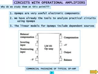
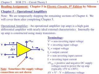
Chapter 5 EGR 271 – Circuit Theory I 1 Reading Assignment: Chapter 5 in Electric Circuits, 9th Edition by Nilsson Chapter 5 – Operational Amplifiers Note: We are temporarily skipping the remaining sections of Chapter 4. We will cover them after completing Chapter 5. Operational Amplifier - An operational amplifier (op amp) is a high gain differential amplifier with nearly ideal external characteristics. Internally the op amp is constructed using many transistors. Terminology: V+ = non-inverting input voltage V- = inverting input voltage Vo = output voltage Io = output current I+ = non-inverting input current I- = inverting input current VDC = positive and negative DC supply voltages used to power the op amp (typically 5V to 30V) V = V+ - V- = difference voltage Note: Sometimes the supply voltage connections are not shown
Chapter 5 EGR 271 – Circuit Theory I 2 Operational Amplifiers 8-pin package pinout 8-pin package (3D view) uA741 symbol in PSPICE
Chapter 5 EGR 271 – Circuit Theory I 3 Typical Operational Amplifier Schematic
Chapter 5 EGR 271 – Circuit Theory I 4 Open-loop versus closed-loop operation: • Open-loop: • Relatively rare • Op amp specifications may be important • Closed-loop: • Most commonly used • Some sort of feedback from output to input exists • The input voltage, Vin, is defined according to the application
Chapter 5 EGR 271 – Circuit Theory I 5 • An op amp circuit can be easily analyzed using the following ideal • assumptions. • Ideal op-amp assumptions: • Assume that V = 0, so V+ = V- • Assume the input resistance is infinite, so I+ = I- = 0 • Realize the all voltages defined above are node voltages w.r.t. a common ground (as illustrated below) Illustration: Draw an op amp showing a common negative terminal for all node voltages.
Chapter 5 EGR 271 – Circuit Theory I 6 Example: Determine an expression for Vo in the inverting amplifier shown below. Illustrate the results using both DC and AC inputs.
Chapter 5 EGR 271 – Circuit Theory I 7 Load Connections: Vo is typically determined independent of the load (the circuit connected to the output). Once Vo has been determined, it essentially acts like a voltage source to the load. Load Current: Io is the output current for an op amp. It can be found using KCL. Example: Find Vo , I1, V2, and Io below.
Chapter 5 EGR 271 – Circuit Theory I 8 Example: Determine an expression for Vo in the non-inverting amplifier shown below.
Chapter 5 EGR 271 – Circuit Theory I 9 Example: Determine Vo in the inverting summing amplifier shown below. RF V _ 1 R 1 V o V + 2 R 2 V 3 R 3
Chapter 5 EGR 271 – Circuit Theory I 10 RF _ R V o + V 1 R 1 V 2 R 2 V 3 R 3 Example: Determine Vo in the non-inverting summing amplifier shown below.
Chapter 5 EGR 271 – Circuit Theory I 11 Example: Determine VL in the circuit shown below.
Chapter 5 EGR 271 – Circuit Theory I 12 Example: Determine Vo in the circuit shown below.
Chapter 5 EGR 271 – Circuit Theory I 13 Practical Limitations in op amps Operational amplifier circuits are generally easy to analyze, design, and construct and their behavior is fairly ideal. There are, however, some limitations to op amps which the engineer should recognize. There are three primary limitations as well as some minor limitations that will be discussed in later courses. The three primary limitations in op amps are: 1) Limited voltage - In general, the output voltage is limited by the DC supply voltages. 2) Limited current - The output current has a maximum limit set by the manufacturer (check the data sheet). 3) Frequency limitations - Op amp performance may deteriorate significantly as frequency increases (studied in later courses)
Chapter 5 EGR 271 – Circuit Theory I 14 Voltage Limitations Vo for any op amp circuit is limited by the supply voltage. In general, If Vo attempts to exceed these limits, the output is limited to +VDC or -VDC and we say that the op amp is “saturated” or is “in saturation.” Practically, Vo is often about 2V under the supply voltage, or Example: Consider the inverting amplifier shown below (covered earlier). 1) Determine the voltage gain, ACL = Vo/Vin
Chapter 5 EGR 271 – Circuit Theory I 15 2) Determine Vo for various possible values of Vin (fill out the table shown below) 3) Graph Vo versus Vin . Identify the saturation and linear regions of operation. Vo Vin
Chapter 5 EGR 271 – Circuit Theory I 16 R2 _ Vin 2k Vo + • Example: Consider the inverting amplifier shown below (covered earlier). • If R2 = 4k, determine range of values for Vin such that the op am will operate in the linear range • If Vin = 2V, determine R2 (max) such that the op am will operate in the linear range +12V -12V
Chapter 5 EGR 271 – Circuit Theory I 17 4k _ Vin 2k Vo + Example: Sketch Vo (on the same graph) for the circuit shown below if Vin is a triangle wave as specified below. +10V 20V -10V Vin 10V 0V -10V -20V
Chapter 5 EGR 271 – Circuit Theory I 18 Current Limitations The maximum output current, Io for an op amp is specified by the manufacturer. Exceeding this limit will typically destroy the op amp. The output current can be calculated using KCL at the output node. An op amp circuit should be designed to insure that its output current does not exceed the maximum value, Io (max), specified by the manufacturer. Example: If Io (max) is specified at 25 mA by the manufacturer, determine the minimum value of RL that can safely be used in the circuit shown below.
Chapter 5 EGR 271 – Circuit Theory I 19 Using node equations to analyze op amp circuits As op amp circuits become more complex, simultaneous equations may be needed to analyze them. Node equations are a natural choice since many op amp voltages are expressed as node voltages. Note: Writing a KCL (node) equation at the output node is not typically helpful except to find Io since it introduced another unknown (Io). Example: Determine Vo in the circuit shown below. Note: Writing a KCL equation (node equation) at the output is only helpful for finding Io since it introduces another unknown (Io).
Chapter 5 EGR 271 – Circuit Theory I 20 Example: Determine Vo in the circuit shown below.
Chapter 5 EGR 271 – Circuit Theory I 21 Example: The circuit shown below is a current amplifier. Determine an expression for IL . Also find the current gain, AI = IL/IS.
Chapter 5 EGR 271 – Circuit Theory I 22 Op amp models So far we have analyzed op amps using a few ideal assumptions about op amps (such as V+ = V- and I+ = I- = 0) . How would we convey these assumptions to a Circuit Theory I program like PSPICE? Typically, we would construct a circuit model that acts like the op amp that we desire. A simple op amp model is shown below. Also note that PSPICE can be used to model op amps with specific part numbers (such as the uA741 in the PSPICE library EVAL.SLB). In these cases, ORCAD develops very detailed circuit models that match the characteristics of the particular op amp. The ORCAD model might look like the model shown below plus additional components to more accurately model additional features. Typical values for the op amp model shown: AOL = 100,000 Rin = 2M - 10M
Chapter 5 EGR 271 – Circuit Theory I 23 Example: Determine Vo in the circuit shown in two ways: 1) by making ideal op amp assumptions
Chapter 5 EGR 271 – Circuit Theory I 24 Example: Determine Vo in the circuit shown in two ways: 2) by using an ideal op amp model with Rin = 2M and AOL = 100,000.
Chapter 5 EGR 271 – Circuit Theory I 25 Analyzing operational amplifier circuits using PSPICE: There are two ways to analyze op amp circuits using PSPICE. 1) Use the general op amp model just introduced (consisting of a resistor and a voltage-controlled voltage source. 2) Use one of the op amp models from a PSPICE library (such as the uA741). Refer to two examples on the course web site: 1) Op Amp Example using a General Op Amp Model 2) Op Amp Circuit using a Library Model ( uA741) Note: End of Test #2 material here.