Download
1 / 60
680 likes | 1.34k Vues
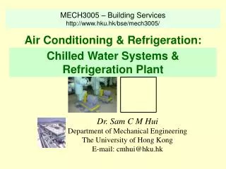
MECH3005 – Building Services http://www.hku.hk/bse/mech3005/. Air Conditioning & Refrigeration:. Chilled Water Systems & Refrigeration Plant. Dr. Sam C M Hui Department of Mechanical Engineering The University of Hong Kong E-mail: cmhui@hku.hk. Contents. Basics of Water Systems

E N D
MECH3005 – Building Services http://www.hku.hk/bse/mech3005/ Air Conditioning & Refrigeration: Chilled Water Systems & Refrigeration Plant Dr. Sam C M Hui Department of Mechanical Engineering The University of Hong Kong E-mail: cmhui@hku.hk
Contents • Basics of Water Systems • Water Piping • Chilled Water Loops • Refrigerants • Refrigeration Cycles • Refrigeration Systems
Basics of Water Systems • Types of water systems • Chilled water (chw) system • Evaporative-cooled water system • Hot water system • Dual-temperature water system • Condenser water system • Sea-water system • Classification • Closed system, open system, once-through system
Basics of Water Systems • Chilled water temperatures • chw leaving should not be < 4 oC (prevent freezing) • Otherwise, brine or glycol-water is used • Smaller Δt, greater the water flow, pipe size & pump power • For typical comfort HVAC: • chw leaving temp = 4.4 to 7.2 oC • Δt = 6.6 to 13.3 oC • For cold air distribution: chw leaving temp = 1.1 oC
Water Piping • Pressure drop • Frictional loss = 0.75 to 4 m / 100 m pipe length • Often assume 2.5 m / 100 m pipe length • Friction charts for steel, copper & plastic pipes for closed water systems (see notes) • Piping materials • Chilled water: black & galvanized steel • Hot water: black steel, hard copper • Condenser water: black steel, galvanized ductile iron, PVC
Water Piping • Steel pipe jointing • Small diameter: threaded cast-iron fittings • Diameter > 50 mm, welded joints & bolted flanges • Max. allowable working pressure for steel & copper pipes = 860 to 2,756 kPa • Design for thermal expansion/contraction • U-, Z- and L-bends, loops & expansion joints • External pipe insulation
2-pipe direct return 2-pipe reverse return
Chilled Water Loops • Plant loop (at constant flow) (production loop) • To protect evaporator from freezing, a fairly constant-volume water flow is required • Building loop (at variable flow) • For saving energy at partload • A differential pressure transmitter is often installed at the farthest end from the pump • Primary-secondary loop • A short common pipe connects the 2 loops
Chilled Water Loops • Control features for chiller capacity • Provide variable flow at building loop • Saves pump power at part load • Separate plant and building loops • Make design, O&M and control simpler, more stable • Plant-distribution-building-loop • Such as in our HKU campus (scattered plants) • Combine with many building loops through a distribution loop
Chilled water system using a plant-distribution-building loop
Chilled Water Loops • Plant-distribution-building loop • Reliable in operation • Require less maintenance • Has minimal environmental impact • Sometimes provide energy cost savings • Small pressure gradient & end pressure differential between distribution supply & return mains • Design practice • A larger diameter pipe; direct return
Refrigerants • Refrigeration • The cooling effect of the process of extracting heat from a lower temperature heat source, a substance or cooling medium, and transferring to a higher temperature heat sink, to maintain the temperature of the heat source below that of surroundings • Refrigeration systems • Combination of components, equipment & piping connected to produce the refrigeration effect
Refrigerants • Refrigeration system • Vapour compression • Mechanical refrigeration using compressors, condensers and evaporators • Absorption • Produce refrigeration effect by thermal energy input • Liquid refrigerant produce refrigeration during evaporation; the vapour is absorbed by an aqueous absorbent • Gas expansion • Air or gas is compressed to a high pressure • It is then cooled by surface water or air and expanded to low pressure to produce refrigeration effect
Vapour compression system Absorption system
Refrigerants • Terminology • Refrigerant: • a primary working fluid to produce refrigeration in a refrigeration system • Cooling medium: • working fluid cooled by refrigerant during evaporation to transport refrigeration from a central plant to remote equipment • Liquid absorbent: • working fluid to absorb vaporised refrigerant (water) after evaporation in an absorption refrigeration system
Refrigerants • Numbering system for refrigerants • For hydrocarbons & halocarbons (halogenated) • ANSI/ASHRAE Standard 34-1992 • 1st digit: number of unsaturated carbon-carbon bonds • 2nd digit: number of carbon atoms minus one • 3rd digit: number of hydrogen atoms plus one • Last digit: number of fluorine atoms • For example, R-11 = CFCl3 ; R-12 = CF2Cl2 ; R-22 = CHF2Cl; R-123 = CHCl2CF3 • Chlorofluorocarbons (CFCs) • Contains only chlorine, fluorine & carbon atoms • Cause ozone depletion & global warming
Refrigerants • Classification of refrigerants • Ozone depletion potential (ODP) • Ratio of ozone depletion rate compared with R-11 • Global warming potential (GWP) • Global warming effect compared with R-11 • Hydrofluorocarbons (HFCs) • Contains only hydrogen, fluorine, and carbon atoms and cause no ozone depletion • R-134a, R-32, R-125 and R-245ca
Refrigerants • HFC’s azeotropic blends or azeotropic • Azeotropic = mixture of multiple refrigerants that evaporate & condense as a single substance and do not change in volumetric composition or saturation temperature when evaporate or condense • ASHRAE assign numbers 500 to 599 for azeotropic • Such as R-507 (blend of R-125/R-143) • HFC’s near azeotropic • Mixture of refrigerants whose characteristics are near those of an azeotropic • ASHRAE assign numbers 400 to 499 for zeotropic • Such as R-404A (R-125/R-134a/R-143a) and R-407B (R-32/R-125/R-134a)
Refrigerants • Zeotropic or non-azeotropic • Including near azeotropic • Show a change in composition due to the difference between liquid & vapour phases, leaks, and the difference between charge & circulation • A shift in composition causes change in evaporating & condensing temperature/pressure • Middle between dew point & bubble point is often taken as evap. & cond. Temp. for the blends
Refrigerants • Hydrochlorofluorocarbons (HCFCs) • Contain hydrogen, chlorine, fluorine & carbon atoms and are not fully halogenated • Smaller lifetime in atmosphere than CFCs & cause far less ozone depletion (ODP = 0.02 to 0.1) • R-22, R-123, R-124 • HCFC’s near azeotropic & HCFC’s zeotropic • Blends of HCFCs with HFCs • Transitional or interim refrigerants, scheduled for restricted production starting in 2004
Refrigerants • Inorganic compounds • Ammonia R-717, water R-178 and air R-729 • Do not deplete ozone layer • ASHRAE assign numbers 700 to 799 • CFCs • Long lifetime (centuries) • Cause ozone depletion (ODP = 0.6 – 1) • Such as R-11, R-12, R-113, R-114, R-115
Refrigerants • Halons (or BFCs) • Contain bromide, fluorine & carbon atoms • R-13B1, R-12B1 (used in very low temp. systems) • Very high ozone depletion (ODP for R-13B1 =10) • Montreal Protocol (1987) & Vienna Convention (1985) • Restrict the production & consumption of CFCs & BFCs • Phase-out of CFCs, BFCs, HCFCs and their blends
Refrigerants • In early 1990s • R-11: widely used for centrifugal chillers • R-12: for small & medium systems • R-22: for all vapour compression systems • R-502 (CFC/HCFC blend) for low-temp. systems • Hong Kong • Ozone Layer Protection Ordinance • See website of Environmental Protection Dept.
Refrigerants • Alternative refrigerants • R-123 (HCFC, ODP = 0.02), replace R-11 • R-245a (ODP = 0), replace R-11 (longer term?) • R-134a (HFC, ODP = 0), replace R-12 • Not miscible with mineral oil, synthetic lubricant is used • R404A (R-125/R-134a/143a) and R-407C • HFCs near azeotropic, ODP = 0; long-term alternatives to R-22 • R-507 (R-125/R-134a) • HFC’s azeotropic, ODP = 0; long-term alternatives to R-502 • Synthetic lubricant oil is used • R-402A (R-22/R-125/R-290) as short-term drop-in replacement
Refrigerants • Required properties of refrigerants • Safety (ANSI/ASHRAE Standard 34-1992) • Toxicity: Class A and Class B • Flammability: • Class 1 – no flame propagation • Class 2 – lower flammability • Class 3 - higher flammability • Such as “A1” Group: R-134a & R-22; “B2”: ammonia • Effectiveness of refrigeration cycle (kW/TR) • Lubricant oil miscibility • Compressor displacement
Refrigerants • Desired properties: • Evaporative pressure > atmospheric • Non-condensable gas will not enter the system • Lower condensing pressure (lighter construction) • High thermal conductivity (better heat transfer) • Dielectric constant compatible w/ air • An inert refrigerant (avoid corrosion, erosion) • Refrigerant leakage can be detected
Refrigeration Cycles • Refrigeration process • Change of thermodynamic properties and the energy & work transfer • 1 ton of refrign. (TR) = 12,000 Btu/h (3.516 kW) • Refrigeraton cycles • Closed cycle and open cycle • Vapour compression cycles: • Single-stage, multi-stage, compound, cascade • Pressure-enthalpy (p-h) diagram
Refrigeration Cycles • Ideal single-stage cycle • Isentropic compression, pressure losses neglected • qrf = refrigeration capacity • Win = work input to compressor • Coefficient of performance (COP) • COP = qrf / Win • Refrigerator: produce refrigeration effect • Heat pump: produce heating effect • Subcooling and superheating
Refrigeration Cycles • Two-stage compound systems w/ flash cooler • Multi-stage compression connected in series • Higher compression efficiency, greater refrig. effect • Compressor ratio • Flash cooler: an economizer to subcool liquid refrigerant to saturated temperature
Refrigeration Cycles • Casade system characteristics • Two independently operated single-stage systems • Connected by a cascade condenser • Main advantages • Different refrigerants, oils and equipment can be used • Disadvantages: more complicated
Refrigeration Systems • Classification of refrigeration systems • Direct expansion (DX) systems & heat pumps • Centrifugal chillers • Screw chillers • Absorption systems • Either single-stage or multistage
Refrigeration Systems • Direct expansion (DX) systems • Part of the packaged A/C system • R-22 and R-134a widely used • Range 3-100 TR • Components & accessories • Compressor(s): reciprocating and scroll • Condensers • Refrigeration feed • Oil lubrication • Refrigerant piping
Cooling mode Heating mode Direct expansion (DX) system