Space Frame Structures for SNAP
Space Frame Structures for SNAP. Bruce C. Bigelow University of Michigan Department of Physics 11/04/04. Space Frames for SNAP. SNAP already has baseline primary and secondary structures. Why look at others? Minimizing structure mass = mission flexibility

Space Frame Structures for SNAP
E N D
Presentation Transcript
Space Frame Structures for SNAP Bruce C. Bigelow University of Michigan Department of Physics 11/04/04
Space Frames for SNAP SNAP already has baseline primary and secondary structures. Why look at others? • Minimizing structure mass = mission flexibility • Higher resonant frequencies are (almost) always better • Minimizing carbon fiber mass reduces H2O dry-out issues • Open structures provide maximum access to payloads • Space frame structures are prevalent in space (heritage)
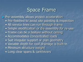
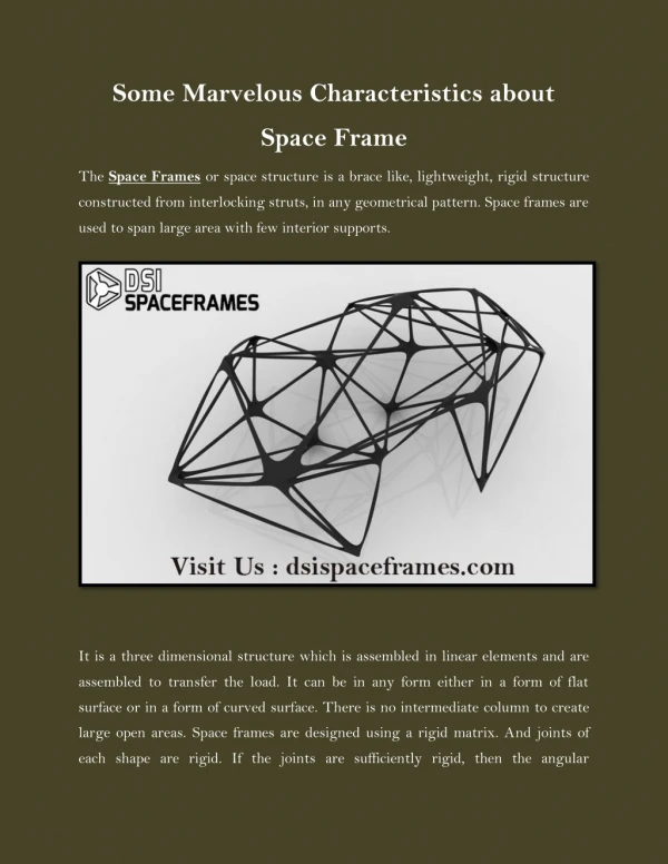
Space Frames Features: • Loads carried axially (ideally) • Joints/nodes carry some moments (not space truss) • Deflections scale linearly with length: • d = PL/AE loads carried in tension/comp. (SF) • Versus: • d = PL/nAG loads carried in shear (monocoque) • d = PL^3/nEI loads carried in bending • Fast and easy to model with FEA • Facilitate test and integration • Space frames are ideal for supporting discrete loads • Space frames make poor fuel tanks and fuselages…
Space Frames for SNAP Status of space frames for SNAP (PPT presentations in BSCW PS1300/Weekly): • Space frame spectrograph mount 05/14/04 • Athermal (constant length) strut designs 06/04/04 • Det. space frame designs for TMA-63 07/29/04 • Indet. Space frame designs for TMA-65 08/26/04 • Node/joint design concepts 09/02/04 • Survey of space heritage structures 09/02/04 • Minimum obscuration SMA structure 09/16/04 • TMA 65, fold mirror, and lower baffle 10/28/04
Spectrograph mount Design features: • Hexapod space frame to carry 10Kg spectrograph • 2:1 hexapod geometry => horizontal deflections, no tilts • Attaches to common focal plane mounting points • Essentially no loads carried by focal plane assembly • Simple interface to spectrograph • 3 discrete support points, or round flange • Supports spectrograph load near center of mass • Minimizes moment loads • Simple interface to FP (mount points, cylindrical volumes) • Spectrograph and mount easily separate from FPA • Invar, CF, or athermal struts • Simple control of spectrograph thermal defocus
FEA Model • SNAP Baseline design: • Moly, Invar, Ti flexures • Attaches to FPA baseplate • Loads carried near detect. • Natural frequencies for spectrograph, mount, and flexures: 116, 121, 164 Hz. • Mass: ?
Spectrograph mounting structure Ease of access to detector connections FP assembly with spectrograph included (note redundant str.)
Dynamic FEA • First 6 freq: • 413 Hz • 415 Hz • 416 Hz • 470 Hz • 478 Hz • 490 Hz f1 = 413 Hz, transverse mode, 25 x 2 mm Invar struts, 2.5 Kg, f1 = 675 Hz for carbon fiber (MJ55), 25 x 2 mm struts, 0.5Kg
Athermal Struts Design features: • Thermally compensated or controlled length struts • 3 materials to provide varying expansion/contraction • Avoid high stresses due to CTE mismatches • Provide integral flexures for kinematic constraints • Provide features for length adjustments (alignment) • Application details required for FEA
Athermal Struts Blue = Ti CP Grade 1 --- 17 PPM/K Light Grey = Invar --- 1.26 PPM/K Dark Grey = Ti 6Al 4V --- 6.7 PPM/K L1 = 156mm, L2 = 78mm, L3 =222mm(x2), 600mm long strut
Athermal Struts 2:1 truss geometry on focal plane assy, 600mm long struts EDM cross-flexure
OTA Space Frames Motivations: • Minimize telescope structure deflections under gravity • Maximize resonant frequencies on ground and in orbit • Minimize structure mass, CF outgassing, etc. • Maximum access to optical elements (assembly, test) • Explore parameter space for SNAP structure
OTA Space Frames – TMA 63 Design objectives: • Maintain symmetry to extent possible • Locate nodes for access to primary loads • 3 nodes above secondary mirror for hexapod mount • 3 nodes above primary for secondary support • 3 nodes behind primary for mirror, attach to SC • 3 nodes below tertiary axis to stabilize secondary supp. • Locate nodes and struts to avoid optical path • Size struts to minimize mass and deflections • Round struts used for constant stiffness vs. orientation • Non-tapered struts used – easy for first cut designs • COI M55J carbon fiber composite used for all struts • CF can be optimized for cross section, thermal expansion
TMA-63 structure FEA Elements
Dynamic FEA Dynamic analyses: Telescope mass: 360kg payload, 96kg structures Modal analysis for ground, launch f1 = 72 Hz f2 = 74 Hz f3 = 107 Hz f4 = 114 Hz f5 = 131 Hz Modal analysis for on-orbit (unconstrained) f7 = 106 Hz f8 = 107 Hz
Static FEA First ground mode, 72 Hz
Nodes for space frames Design features: • Nodes connect the struts in a space frame • Accommodate diameters of struts (constant diameter, wall) • Minimize mass (often a large fraction of the mass in a SF) • Maximize ease of fabrication and assembly • Provide attachment points for secondary structures
Nodes for space frames • Molded node, 22mm x 2mm tubes, V = 13103 mm^3 • Invar = 0.1 Kg, Ti = 0.06 Kg, CC = 0.02 Kg
Nodes for space frames • Machined node, 22mm OD tubes, V = 58561 mm^3 • Invar = .47 Kg, Ti = 0.26 Kg, CC = 0.09 Kg
Secondary Mirror Structure Design features: • Minimize pupil obscuration by SMA structures • Minimize structure mass • Maintain high first resonance • Secondary support vanes: • 25 mm diameter x 2 mm wall • Requires revisions to current outer baffle design
Secondary Structure Blue/green hexapod struts are outside of CA
Secondary Structure Trial 9, ring at 2.85m elev.
Space frame developments Latest work: • TMA 65 structure with nodes • Fold mirror sub-frame • Lower baffle structure (Al) and close-outs • Rings have 50 x 50 x 3 mm sections • Struts have 50 x 50 x 6mm sections • Upper baffle mass = 190 Kg • Baffle structure (38 Kg) + close-outs (27 Kg) = 65 Kg • f1 = 33 Hz • CF baffle structure: 20Kg, 40Hz
Deformation in 1g held by GSE(baffle displacement~2.6mm) Baseline: mass = 79 Kg
Lower baffle structure mass = 65 Kg
Space frames for SNAP Conclusions: • Space frames are applicable to most SNAP structures • Space frame structures offer significant mass reductions over current baseline designs • Space frame structures provide higher frequencies/mass compared to baseline designs • Space craft structure heritage is well established • Space frame structures will readily scale to larger apertures • Space frames for SNAP: Ready for prime time!