The Data Link Layer
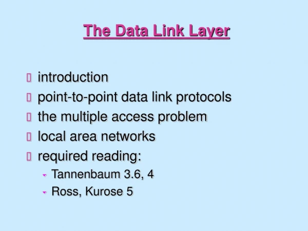
The Data Link Layer. Chapter 3. 3.1 Data Link Layer Design Issues. Services Provided to the Network Layer Framing Error Control Flow Control. Functions of the Data Link Layer. Provide service interface to the network layer Dealing with transmission errors Regulating data flow


The Data Link Layer
E N D
Presentation Transcript
The Data Link Layer Chapter 3
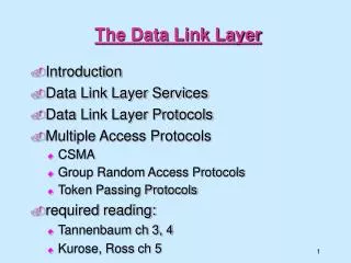
3.1 Data Link Layer Design Issues • Services Provided to the Network Layer • Framing • Error Control • Flow Control
Functions of the Data Link Layer • Provide service interface to the network layer • Dealing with transmission errors • Regulating data flow • Slow receivers not swamped by fast senders
Relationship between packets and frames Fig.3-1 Relationship between packets and frames.
3.1.1 Services Provided to Network Layer The actual transmission follows the path of Fig. 3-2(b), but it is easier to think in terms of two data link layer processes communicating using a data link protocol. For this reason, we will implicitly use the model of Fig. 3-2(a) throughout this chapter. Fig.3-2 (a) Virtual communication. (b) Actual communication.
Services Provided to Network Layer The data link layer can be designed to offer various services. Three reasonable possibilities that are commonly provided are 1.Unacknowledged connectionless service. 2. Acknowledged connectionless service. 3. Acknowledged connection-oriented service.
Services Provided to Network Layer Fig.3-3 Placement of the data link protocol.
3.1.2 Framing To provide service to the network layer, the data link layer must use the service provided to it by the physical layer. What the physical layer does is accept a raw bit stream and attempt to deliver it to the destination. This bit stream is not guaranteed to be error free. The number of bits received may be less than, equal to, or more than the number of bits transmitted, and they may have different values. It is up to the data link layer to detect and, if necessary, correct errors. The usual approach is for the data link layer to break the bit stream up into discrete frames and compute the checksum for each frame. (Checksum algorithms will be discussed later in this chapter.) When a frame arrives at the destination, the checksum is recomputed. If the newly-computed checksum is different from the one contained in the frame, the data link layer knows that an error has occurred and takes steps to deal with it (e.g., discarding the bad frame and possibly also sending back an error report). Breaking the bit stream up into frames is difficult. In this section we will look at four methods: • Character count. • Flag bytes with byte stuffing. • Starting and ending flags, with bit stuffing. • Physical layer coding violations.
Character count Fig.3-4 A character stream. (a) Without errors. (b) With one error.
Flag bytes with byte stuffing Fig.3-5 (a) A frame delimited by flag bytes. (b) Four examples of byte sequences before and after stuffing.
Starting and ending flags, with Bit stuffing Each frame begins and ends with a special bit pattern, 01111110.Whenever the sender's data link layer encounters five consecutive 1s in the data, it automatically stuffs a 0 bit into the outgoing bit stream. When the receiver sees five consecutive incoming 1 bits, followed by a 0 bit, it automatically destuffs (i.e., deletes) the 0 bit. Fig.3-6 (a) The original data. (b) The data as they appear on the line. (c) The data as they are stored in receiver’s memory after destuffing.
3.1.3 Error Control • Feedback Receiver sents positive or negative acknowledgementsto sender • Timers To dealt with frame or the acknowledgement lost • Sequence Numbers To prevent receiver passing the same frame to the network layer more than once
3.1.4 Flow Control Prevent a sender to transmit frames faster than the receiver can accept them. • feedback-based flow control • rate-based flow control In the first one, feedback-based flow control, the receiver sends back information to the sender giving it permission to send more data or at least telling the sender how the receiver is doing. In the second one, rate-based flow control, the protocol has a built-in mechanism that limits the rate at which senders may transmit data, without using feedback from the receiver.
3.2 Error Detection and Correction • Error-Correcting Codes Include enough redundant information along with each block of data sent, to enable the receiver to deduce what the transmitted data must have been. Used on unreliable channels , such as wireless links. • Error-Detecting Codes Include only enough redundancy to allow the receiver to deduce that an error occurred, but not which error, and have it request a retransmission. Used on unreliable channels , such as fiber.
Error Detection and Correction Normally, a frame consists of m data bits and r redundant bits. The total length n = m + r referred to as an n-bit codeword. The number of bit positions in which two codewords differ is called the Hamming distance . To detect d errors, you need a distance d + 1 code .To correct d errors, you need a distance 2d + 1 code. Parity code matrix code Hamming code Polynomial code, also known as a CRC (Cyclic Redundancy Check)
3.2.1 Error-Correcting Codes Design a code with m message bits and r check bits that will allow all single errors to be corrected. The total length n=m+r There are n illegal codewords, so we need n + 1 bit patterns to point out n errors and no error. n+1 ≤2r m + r + 1 ≤2r For example, if m=7 then r≥ 4 The bits that are powers of 2 (1, 2, 4, 8, 16, etc.) are check bits. The rest (3, 5, 6, 7, 9, etc.) are filled up with the m data bits. Each check bit forces the parity of some collection of bits. To see which check bits the data bit in position k contributes to, rewrite k as a sum of powers of 2. 11=1+2+8 Bit 11 is checked by bits 1, 2, and 8
Error-Correcting Codes When a codeword arrives, the receiver initializes a counter to zero. It then examines each check bit, k (k = 1, 2, 4, 8, ...), to see if it has the correct parity. If not, the receiver adds k to the counter. If the counter is zero after all the check bits have been examined (i.e., if they were all correct), the codeword is accepted as valid. If the counter is nonzero, it contains the number of the incorrect bit. For example, if check bits 1, 2, and 8 are in error, the inverted bit is 11, because it is the only one checked by bits 1, 2, and 8.
An Example of Hamming Code Fig.3-7 Use of a Hamming code to correct burst errors.
3.2.2 Error-Detecting Codes CRC are based upon treating bit strings as representations of polynomials with coefficients of 0 and 1 only. For example, 110001 has 6 bits and thus represents a six-term polynomial with coefficients 1, 1, 0, 0, 0, and 1: x5 + x4 + x0. The sender and receiver must agree upon a generator polynomial, G(x), degree of r(r bits checksum).
CRC The algorithm for computing the checksum is as follows: 1.Let r be the degree of G(x). Append r zero bits to the low-order end of the frame so it now contains m + r bits and corresponds to the polynomial xrM(x). 2. Divide the bit string corresponding to G(x) into the bit string corresponding to xrM(x), using modulo 2 division. 3. Subtract the remainder (which is always r or fewer bits) from the bit string corresponding to xrM(x) using modulo 2 subtraction. The result is the checksummed frame to be transmitted. Call its polynomial T(x).
Figure 3-8. Calculation of the polynomial code checksum. This figure illustrates the calculation for a frame 1101011011 using the generator G(x) = x4 + x + 1.
3.3 Elementary Data Link Protocols • An Unrestricted Simplex Protocol • A Simplex Stop-and-Wait Protocol • A Simplex Protocol for a Noisy Channel
Protocol Definitions Continued Fig.3-9 Some definitions needed in the protocols to follow. These are located in the file protocol.h.
Protocol Definitions(ctd.) Some definitions needed in the protocols to follow. These are located in the file protocol.h.
3.3.3 A Simplex Protocol for a Noisy Channel A positive acknowledgement with retransmission protocol. Continued
A Simplex Protocol for a Noisy Channel (ctd.) A positive acknowledgement with retransmission protocol.
3.4 Sliding Window Protocols • piggybacking • sending window • receiving window • A One-Bit Sliding Window Protocol • A Protocol Using Go Back N • A Protocol Using Selective Repeat
piggybacking When a data frame arrives, instead of immediately sending a separate control frame, the receiver restrains itself and waits until the network layer passes it the next packet. The acknowledgement is attached to the outgoing data frame (using the ack field in the frame header). The technique of temporarily delaying outgoing acknowledgements so that they can be hooked onto the next outgoing data frame is known as piggybacking. • piggybacking immediately • Waiting for a moment and piggybacking • Sending a separate acknowledgement frame
Sliding Window The essence of all sliding window protocols is that at any instant of time, the sender maintains a set of sequence numbers corresponding to frames it is permitted to send. These frames are said to fall within the sending window. Similarly, the receiver also maintains a receiving window corresponding to the set of frames it is permitted to accept. The frames with sequence numbers within the sender's window can be sent. When an acknowledgement comes in, the sliding window is advanced by one. The receiving data link layer's window corresponds to the frames it may accept. Any frame falling outside the window is discarded. When a frame whose sequence number is equal to the lower edge of the window is received, it is passed to the network layer, an acknowledgement is generated, and the window is rotated by one.
3.4.1 A One-Bit Sliding Window Protocol A sliding window protocol with a maximum window size of 1 is called a one-bit sliding window protocol. Such a protocol uses stop-and-wait since the sender transmits a frame and waits for its acknowledgement before sending the next one. Fig.3-13 A sliding window of size 1, with a 3-bit sequence number. (a) Initially. (b) After the first frame has been sent. (c) After the first frame has been received. (d) After the first acknowledgement has been received.
3.4.2 A Protocol Using Go Back N The sender is be able to continuously transmit frames before blocking. When a frame is in error or lost, the sender have to retransmit the frame and the frames transmitted after that frame.
3.4.3 A Protocol Using Selective Repeat The sender is be able to continuously transmit frames before blocking. When a frame is in error or lost, the sender only retransmit the frame in error.
Example of Sliding Windows Fig.3-16 Pipelining and error recovery. Effect on an error when (a) Receiver’s window size is 1. (b) Receiver’s window size is large.
A Sliding Window Protocol Using Selective Repeat Fig.3-20 (a) Initial situation with a window size seven. (b) After seven frames sent and received, but not acknowledged. (c) Initial situation with a window size of four. (d) After four frames sent and received, but not acknowledged.
The Relationship between the Size of Sliding Window and Protocol If the size of sending window is one,and the size of receiving window is one, the protocol is stop-and-wait protocol (one bit sliding window protocol). If the size of sending window is larger then one,and the size of receiving window is one, the protocol is go back N. If the size of sending window is larger then one,and the size of receiving window is larger then one, the protocol is selective repeat.
3.6 Example Data Link Protocols • HDLC – High-Level Data Link Control • The Data Link Layer in the Internet
3.6.1 High-Level Data Link Control In this section we will examine a group of closely related protocols that are a bit old but are still heavily used. They are all derived from the data link protocol first used in the IBM mainframe world: SDLC (Synchronous Data Link Control) protocol. After developing SDLC, IBM submitted it to ANSI and ISO for acceptance as U.S. and international standards, respectively. ANSI modified it to become ADCCP (Advanced Data Communication Control Procedure), and ISO modified it to become HDLC (High-level Data Link Control). CCITT then adopted and modified HDLC for its LAP (Link Access Procedure) as part of the X.25 network interface standard but later modified it again to LAPB, to make it more compatible with a later version of HDLC. These protocols are based on the same principles. All are bit oriented, and all use bit stuffing for data transparency. They differ only in minor.
Frame Format The Control field is used for sequence numbers, acknowledgements, and other purposes, as discussed below. The Data field may contain any information. It may be arbitrarily long, although the efficiency of the checksum falls off with increasing frame length due to the greater probability of multiple burst errors. The Checksum field is a cyclic redundancy code using the technique we examined in Sec. 3-2.2. The frame is delimited with another flag sequence (01111110). On idle point-to-point lines, flag sequences are transmitted continuously. The minimum frame contains three fields and totals 32 bits, excluding the flags on either end. Fig.3-24 Frame format for bit-oriented protocols.
Three Kinds of Frames Fig.3-25 Control field of (a) An information frame. (b) A supervisory frame. (c) An unnumbered frame.
Three Kinds of Frames The P/F bit stands for Poll/Final. When used as P, the computer is inviting the terminal to send data. All the frames sent by the terminal, except the final one, have the P/F bit set to P. The final one is set to F. Type field of Supervisory frames : Type 0 is an acknowledgement frame , called RECEIVE READY. It calls for retransmission of all outstanding frames starting at Next . Type 1 is a negative acknowledgement frame called REJECT. Type 2 tells the sender to stop sending, called RECEIVE NOT READY. Type 3 is the SELECTIVE REJECT. It calls for retransmission of only the frame specified.
High-Level Data Link Control (4) Three Kinds of Frames Unnumbered frame type : DISC allows a machine to announce that it is going down. SNRM (Set Normal Response Mode) is an unbalanced (i.e., asymmetric) mode in which one end of the line is the master and the other the slave. SABM (Set Asynchronous Balanced Mode) resets the line and declares both parties to be equals. FRMR(FRaMe Reject) indicates that a frame with a correct checksum but impossible semantics arrived. UA (Unnumbered Acknowledgement) is provided for acknowledged of commands.
SAMB,P B A UA I,0,0 I,1,0 I,2,0 I,3,0 I,0,2 I,1,3 I,4,2 X I,5,2 I,6,2 REJ,4 I,4,2 I,5,2 I,6,2 RNR,7 RR,7 I,7,2 I,0,2 DISC,P UA,F
3.6.2 The Data Link Layer in the Internet The Internet consists of individual machines (hosts and routers) and the communication infrastructure that connects them. Within a single building, LANs are widely used for interconnection, but most of the wide area infrastructure is built up from point-to-point leased lines. In Chap. 4, we will look at LANs; here we will examine the data link protocols used on point-to-point lines in the Internet. In practice, point-to-point communication is primarily used in two situations. First, thousands of organizations have one or more LANs, each with some number of hosts (personal computers, user workstations, servers, and so on) along with a router (or a bridge, which is functionally similar). Often, the routers are interconnected by a backbone LAN. Typically, all connections to the outside world go through one or two routers that have point-to-point leased lines to distant routers. The second situation in which point-to-point lines play a major role in the Internet is the millions of individuals who have home connections to the Internet using modems and dial-up telephone lines.
The Data Link Layer in the Internet Fig.3-26 A home personal computer acting as an internet host.
PPP – Point to Point Protocol PPP handles error detection, supports multiple protocols, allows IP addresses to be negotiated at connection time, permits authentication, and has many other features. PPP provides three features: A framing method that unambiguously delineates the end of one frame and the start of the next one. A link control protocol for bringing lines up, testing them, negotiating options, and bringing them down again gracefully when they are no longer needed. This protocol is called LCP (Link Control Protocol). A way to negotiate network-layer options in a way that is independent of the network layer protocol to be used. The method chosen is to have a different NCP (Network Control Protocol) for each network layer supported.
PPP – Point to Point Protocol The PPP frame format was chosen to closely resemble the HDLC frame format, since there was no reason to reinvent the wheel. The major difference between PPP and HDLC is that PPP is character oriented rather than bit oriented. In particular, PPP uses byte stuffing on dial-up modem lines, so all frames are an integral number of bytes. It is not possible to send a frame consisting of 30.25 bytes, as it is with HDLC. The PPP frame format is shown in Fig. 3-27. Fig.3-27 The PPP full frame format for unnumbered mode operation.
PPP – Point to Point Protocol All PPP frames begin with the standard HDLC flag byte (01111110), which is byte stuffed if it occurs within the payload field. Next comes the Address field, which is always set to the binary value 11111111 to indicate that all stations are to accept the frame. Using this value avoids the issue of having to assign data link addresses. The Address field is followed by the Control field, the default value of which is 00000011. This value indicates an unnumbered frame. In other words, PPP does not provide reliable transmission using sequence numbers and acknowledgements as the default. In noisy environments, such as wireless networks, reliable transmission using numbered mode can be used. Since the Address and Control fields are always constant in the default configuration, LCP provides the necessary mechanism for the two parties to negotiate an option to just omit them altogether and save 2 bytes per frame. The fourth PPP field is the Protocol field. Its job is to tell what kind of packet is in the Payload field. Codes are defined for LCP, NCP, IP, IPX, AppleTalk, and other protocols. The default size of the Protocol field is 2 bytes, but it can be negotiated down to 1 byte using LCP. The Payload field is variable length, up to some negotiated maximum. If the length is not negotiated using LCP during line setup, a default length of 1500 bytes is used. After the Payload field comes the Checksum field, which is normally 2 bytes, but a 4-byte checksum can be negotiated.