Download
1 / 33
330 likes | 523 Vues
2010 Conference on Indium Phosphide and Related Materials, June 2-4, Takamatsu, Japan. III-V MOSFETs: Scaling Laws, Scaling Limits,Fabrication Processes. Mark. Rodwell, University of California, Santa Barbara.

E N D
2010 Conference on Indium Phosphide and Related Materials, June 2-4, Takamatsu, Japan III-V MOSFETs: Scaling Laws, Scaling Limits,Fabrication Processes Mark. Rodwell, University of California, Santa Barbara A. D. Carter, G. J. Burek, M. A. Wistey*, B. J. Thibeault, A. Baraskar, U. Singisetti, J. Cagnon, S. Stemmer, A. C. Gossard, C. PalmstrømUniversity of California, Santa Barbara*Now at Notre Dame B. Shin, E. Kim, P. C. McIntyreStanford University Y.-J. LeeIntel B. Yue, L. Wang, P. Asbeck, Y. TaurUniversity of California, San Diego
III-V MOSFETs for VLSI: Why and Why Not. Lower mass → Higher Carrier Velocity→ lower input capacitance improved gate delay in transistor-capacitance-limited gates not relevant in wiring-capacitance-limited gates (i.e. most of VLSI) More importantly: potential for higher drive current improved gate delay in wiring-capacitance-limited gates (VLSI) But this advantage is widely misunderstood in community InGaAs channels→ higher Id / Wg than Si only for thick dielectrics ....LOWER Id / Wg than Si for thin dielectrics break-even point is at ~0.5 nm EOT We will introduce later candidate III-V channel designs providing higher Id / Wg than Si even for small EOT
III-V MOS: What is needed ? True MOS device structures at ~10 nm gate lengths 10nm gate length, < 10nm electrode spacings, < 10nm contact widths < 3 nm channel, < 1 nm gate-channel separation, < 3nm deep junctions Fully self-aligned processes: N+ S/D, S/D contacts Drive currents >> 1 mA/micron @ 1/2-Volt Vdd. Low access resistances. Density-of-states limits. Dielectrics: < 0.6 nm EOT , Dit < 1012 /cm2-eV impacts Ion, Ioff , ... Low dielectric Dit must survive FET process. ...and the channel must be grown on Silicon
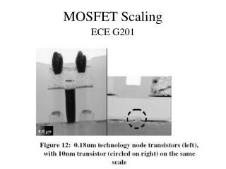
Requirements: 10 nm Lg III-V MOSFET Self-aligned S/D contactslow resistance in ~10 nm width,< 0.5 W-mm2 resistivity needed. Self-aligned N+ source/drain shallow, heavily-dopedaligned within nm of gate Thin oxide < 1 nm EOTThin channel < 5nmShallow channel: no setbacks Lg LS/D IBM High-k Metal gate transistor Image Source: EE Times
InGaAs MOSFET with N+ Source/Drain by MEE Regrowth1 HAADF-STEM1* InGaAs regrowth Interface InGaAs 2 nm * TEM by J. Cagnon, Susanne Stemmer Group, UCSB Self-aligned source/drain defined by MBE regrowth2 Self-aligned in-situ Mo contacts3 Process flow & dimensions selected for 10-30 nm Lg design; Gate-first gate dielectric formed after MBE growth uncontaminated / undamaged surface 1Singisetti, ISCS 20082Wistey, EMC 20083Baraskar, EMC 2009
Process flow* * Singisetti et al, 2008 ISCS, September, Frieburg Singisetti et al; Physica Status Solidi C, vol. 6, pp. 1394,2009
Key challenge in S/D process: gate stack etch Requirement: avoid damaging semiconductor surface: Approach: Gate stack with multiple selective etches* FIB Cross-section Damage free channel SiO2 Cr W Process scalable to ~10 nm gate lengths * Singisetti et al; Physica Status Solidi C, vol. 6, pp. 1394,2009
MBE Regrowth→ Gap Near Gate→ Source Resistance Ti/Au Pad SiO2 cap SEM Mo+InGaAs W / Cr / SiO2 gate W/Cr gate Gap in regrowth SEM • Shadowing by gate: No regrowth next to gate • Gap region is depleted of electrons W / Cr / SiO2 gate High source resistance because of electron depletion in the gap MBE growth by Dr. Mark Wistey, device fabrication and characterization by U. Singisetti
Migration Enhanced Epitaxial (MEE) S/D Regrowth* High T migration enhanced Epitaxial (MEE) regrowth* 45o tilt SEM No Gap Top of SiO2 gate gate Side of gate regrowth interface No Gap High temperature migration enhanced epitaxial regrowth *Wistey, EMC 2008 Wistey, ICMBE 2008 MBE growth by Dr. Mark Wistey, device fabrication and characterization by U. Singisetti
Regrowth profile dependence on As flux* SiO2 InAlAs InGaAs InGaAs increasingAs flux Cr 5.6x10⁻⁷, 1.0x10-6,2x10-6 , 5x10⁻⁶ Torr540 °C growth InGaAs W InGaAs regrowth surface uniform filling multiple InGaAs regrowths with InAlAs marker layers Uniform filling with lower As flux * Wistey et al, EMC 2009 Wistey et al NAMBE 2009 MBE growth by Dr. Mark Wistey, device fabrication and characterization by U. Singisetti
InAsregrowth Gate InAs source/drain regrowth top of gate side of gate Mo S/D metal with N+ InAs underneath Improved InAs regrowth with low As flux for uniform filling1 InAs less susceptible to electron depletion: Fermi pinning above Ec2 1 Wistey et al, EMC 2009 Wistey et al NAMBE 2009. 2Bhargava et al , APL 1997
InGaAs regrowth InGaAs TEM by Dr. J. Cagnon, Stemmer Group, UCSB In-Situ Refractory Ohmics on MBE Regrown N-InGaAs In-situ Mo on n-InAs In-situ Mo on n-InGaAs ρc = 1.0 ± 0.6 Ω·µm2 n = 5×1019 cm-3 ρc = 0.6 ± 0.4 Ω·µm2 n = 1×1020 cm-3 HAADF-STEM* Interface Contact resistivityto MEE regrown materialis ~1.2 W-mm2. 2 nm A. Baraskar
Dummy gate No regrowth Self-Aligned Contacts: Height Selective Etching* PR Mo PR PR InGaAs * Burek et al, J. Cryst. Growth 2009
Drive current and transconductance 0.95 mA/mm peak Id , ~0.45 mS/mm peak gm
27 nm Self-Aligned Process Flow Self-aligned structures at ~10 nm gate length can be fabricated MEE regrowth has very narrowprocess window→ CBE or MOCVD ?
FET Scaling Laws Changes required to double device / circuit bandwidth. laws in constant-voltage limit: Current densities should doubleCharge densities must double
Calculating Current: Ballistic Limit Do we get highest current with high or low mass ?
Drive Current Versus Mass, # Valleys, and EOT Standard InGaAs MOSFETs have superior Id to Si at large EOT. Standard InGaAs MOSFETs have inferior Id to Si at small EOT. Solomon / Laux Density-of-States-Blottleneck → III-V loses to Si.
Standard Approach G valleys in [100] orientation 3 nm GaAs wellAlSb barriers Relative Energies:G=0 eVL=177 meVX[100]= 264 meVX[010] = 337 meV
First Approach: Use both G and L valleys in [111] 2.3 nm GaAs wellAlSb barriers[111] orientation Relative Energies:G= 41 meVL[111] (1)= 0 meVL[111] (2)= 84 meVL[11-1] =175 meVX=288 meV
Combined G-L wells in {111} orientation vs. Si combined (G -L) transport GaAs MOSFET with combined G and L transport, 2 nm well→ g=2, m*/m0=0.07 GaSb MOSFET with combined G and L transport, ~4 nm well→ mG*/m0=0.039, mL*/m0=0.1
2nd Approach: Use L valleys in Stacked Wells Three 0.66 nm GaAs wells0.66 nm AlSb barriers [111] orientation Relative Energies:G=338 meVL[111](1) = 0 meVL[111](2)= 61 meVL[111](3)= 99 meV L[11-1] =232 meVX=284 meV
III-V MOS With appropriate design, III-V channels can provide > current than Si ...even for highly scaled devices But present III-V device structures are also unsuitable for 10 nm MOS large access regions, low current densities, deep junctions Raised S/D regrowth process is a path towards a nm VLSI III-V device Gate dielectric still requires major progress...