Download
1 / 45
1.09k likes | 4.11k Vues
Positioning of the Skull. By Prof. Stelmark. RADIOGRAPHIC ANATOMY Skull As with other body parts, radiography of the skull requires a good understanding of all related anatomy. The anatomy of the skull is very complex, and specific attention to detail is required of the technologist.

E N D
Positioning of the Skull By Prof. Stelmark
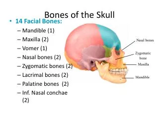
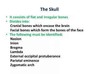
RADIOGRAPHIC ANATOMY Skull As with other body parts, radiography of the skull requires a good understanding of all related anatomy. The anatomy of the skull is very complex, and specific attention to detail is required of the technologist. The skull, or bony skeleton of the head, rests on the superior end of the vertebral column and is divided into two main sets of bones—the 8 cranial bones and the 14 facial bones.
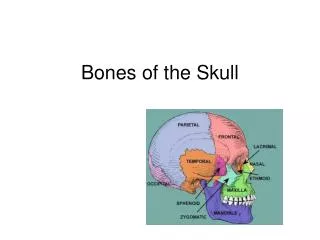
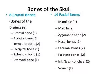
CRANIAL BONES (8) The eight bones of the cranium are divided into the calvaria (skullcap) and the floor. Each of these two areas primarily consists of four bones: Calvaria (Skullcap) 1. Frontal 2. Right parietal 3. Left parietal 4. Occipital Floor 5. Right temporal 6. Left temporal 7. Sphenoid (sfe′-noid) 8. Ethmoid (eth′-moid)
POSITIONING CONSIDERATIONS Erect versus Recumbent Projections of the skull may be taken with the patient in the recumbent or erect position, depending on the patient's condition. Images can be obtained in the erect position with the use of a standard x-ray table in the vertical position or an upright Bucky. The erect position allows the patient to be quickly and easily positioned and permits the use of a horizontal beam. A horizontal beam is necessary to visualize any existing air-fluid levels within the cranial or sinus cavities
Patient Comfort Patient motion almost always results in an unsatisfactory image. During skull radiography, the patient's head must be placed in precise positions and held motionless long enough for an exposure to be obtained. Always remember that a patient is attached to the skull that is being manipulated. Every effort should be made to make the patient's body as comfortable as possible, and positioning aids such as sponges, sandbags, and pillows should be used if needed. Except in cases of severe trauma, respiration should be suspended during the exposure to help prevent blurring of the image caused by breathing movements of the thorax. This is especially important when the patient is in a prone position.
Hygiene Cranial and facial radiography may require the patient's face to be in direct contact with the technologist's hands and the table/upright Bucky surface. Therefore, it is important that proper handwashing techniques and surface disinfectants be used before and after the examination.
Exposure Factors The principal exposure factors for radiography of the skull include the following: •Medium kV (65 to 85 kV film-based) (70 to 80 kV digital radiography [DR] and computed radiography [CR]) •Small focal spot <250 mA (if equipment allows) •Short exposure time
SID The minimum SID with the image receptor in the table or upright Bucky is 40 inches (100 cm). Radiation Protection The best techniques for minimizing radiation exposure to the patient in skull radiography are to (1) use good collimation practices, (2) immobilize the head when necessary, minimizing repeats, and (3) center properly. Gonadal shielding Generally, with accurate collimation, no detectable contribution to gonadal exposure occurs during radiography of the skull. However, lead shields should be used to reassure the patient
Digital Imaging Considerations Guidelines for digital imaging (CR and DR) of the skull are: 1.Correct central ray angle and centering to body part and image receptor. This provides for accurate post-processing of the image by the image reader. 2.Close collimation. Improves image quality by reducing scatter and secondary radiation to the highly sensitive digital image receptors. 3.Following ALARA principles (exposure to patient As Low As Reasonably Achievable) in determining exposure factors (highest kV and lowest mAs that will result in desirable image quality). An increase in kV over film-screen imaging may be desirable, both for reducing patient exposure and for improving image quality. (Sufficient mAs is required to produce a high-resolution image.) 4.Post-processing evaluation of exposure indices (for assurance that optimum quality image was achieved with least possible radiation to patient). Examine the amount of kV and mAs used for a particular exposure if the exposure index is above or below the recommended range.
Skull Series BASIC: • AP axial (Towne method) • Lateral • PA axial 15° (Caldwell method) or PA axial 25° to 30° • PA 0° SPECIAL • Submentovertex (SMV) • PA axial (Haas method)
AP AXIAL PROJECTION: SKULL SERIES Towne Method Pathology Demonstrated Skull fractures
Technical Factors • IR size—24 × 30 cm (10 × 12 inches), lengthwise • Moving or stationary grid • 70 to 80 kV range • Small focal spot
Part Position • Depress chin, bringing OML perpendicular to IR. For patients unable to flex their neck to this extent, align the IOML perpendicular to the IR. Add radiolucent support under the head if needed. • Align midsagittal plane to CR and to midline of the grid or the table/Bucky surface. • Ensure that no head rotation and/or no tilt exists. • Ensure that vertex of skull is in x-ray field.
Collimation Collimate to outer margins of skull. Respiration Suspend respiration. If patient is unable to depress the chin sufficiently to bring the OML perpendicular to the IR even with a small sponge under the head, the infraorbitomeatal line (IOML) can be placed perpendicular instead and the CR angle increased to 37° caudad. This maintains the 30° angle between the OML and the CR and demonstrates the same anatomic relationships. (A 7° difference exists between the OML and the IOML.)
Central Ray • Angle CR 30° caudad to OML, or 37° caudad to IOML (see Note below). • Center at the midsagittal plane 2½ inches (6.5 cm) above the glabella to pass through the foramen magnum at the level of the base of the occiput. • Center IR to projected CR. • Minimum SID is 40 inches (100 cm).
Structures Shown: • Occipital bone, petrous pyramids, and foramen magnum are shown with the dorsum sellae and posterior clinoids visualized in the shadow of the foramen magnum.
LATERAL POSITION—RIGHT AND/OR LEFT LATERAL: SKULL SERIES Pathology Demonstrated Skull fractures. A common general skull routine includes both right and left laterals.
Part Position • Place the head in a true lateral position, with the side of interest closest to IR and the patient's body in a semiprone position as needed for comfort. • Align midsagittal plane parallel to IR, ensuring no rotation or tilt. • Align interpupillary line perpendicular to IR, ensuring no tilt of head (see Note below). • Adjust neck flexion to align IOML perpendicular to front edge of IR
Central Ray • Align CR perpendicular to IR. • Center to a point 2 inches (5 cm) superior to EAM . • Center IR to CR. • Minimum SID is 40 inches (100 cm).
Structures Shown: • Superimposed cranial halves with superior detail of the lateral cranium closest to the IR are demonstrated. The entire sella turcica, including anterior and posterior clinoids and dorsum sellae, is also shown. The sella turcica and clivus are demonstrated in profile.
PA AXIAL PROJECTION: SKULL SERIES 15° CR (Caldwell Method) or 25° to 30° CR Pathology Demonstrated Skull fractures (medial and lateral displacement)
Part Position • Rest patient's nose and forehead against table/Bucky surface. • Flex neck as needed to align OML perpendicular to IR. • Align midsagittal plane perpendicular to midline of the grid or table/Bucky surface to prevent head rotation and/or tilt. • Center IR to CR.
Central Ray • Angle CR 15° caudad and center to exit at nasion. • Alternate with CR 25° to 30° caudad, and center to exit at nasion. • Minimum SID is 40 inches (100 cm).
Alternate 25° to 30°: An alternate projection is a 25° to 30° caudad tube angle that allows better visualization of the superior orbital fissures (black arrows), the foramen rotundum (small white arrows), and the inferior orbital rim region. CR exits at level of nasion.
Structures Shown: • Greater and lesser sphenoid wings, frontal bone, superior orbital fissures, frontal and anterior ethmoid sinuses, superior orbital margins, and crista galli are shown.
PA PROJECTION: SKULL SERIES 0° CR Pathology Demonstrated Skull fractures (medial and lateral displacement)
Part Position • Rest patient's nose and forehead against table/Bucky surface. • Flex neck, aligning OML perpendicular to IR. • Align midsagittal plane perpendicular to midline of table/Bucky to prevent head rotation and/or tilt (EAMs same distance from table/Bucky surface). • Center IR to CR.
Structures Shown: • Frontal bone, crista galli, internal auditory canals, frontal and anterior ethmoid sinuses, petrous ridges, greater and lesser wings of sphenoid.
SUBMENTOVERTEX (SMV) PROJECTION: SKULL SERIES Warning: Rule out cervical spine fracture or subluxation on trauma patient before attempting this projection.
Part Position • Raise patient's chin and hyperextend the neck if possible until IOML is parallel to IR. • Rest patient's head on vertex. • Align midsagittal plane perpendicular to the midline of the grid or table/Bucky surface, thus avoiding tilt and/or rotation.
Central Ray • CR is perpendicular to infraorbitomeatal line. • Center 1½ inch (4 cm) inferior to the mandibular symphysis, or midway between the gonions. • Center image receptor to CR. • Minimum SID is 40 inches (100 cm)
Structures Shown: • Foramen ovale and spinosum, mandible, sphenoid and posterior ethmoid sinuses, mastoid processes, petrous ridges, hard palate, foramen magnum, and occipital bone are shown.
PA AXIAL PROJECTION: SKULL SERIES Haas Method Pathology Demonstrated Occipital bone, petrous pyramids, and foramen magnum, with dorsum sellae and posterior clinoids in its shadow
Part Position • Rest patient's nose and forehead against the table/Bucky surface. • Flex neck, bringing OML perpendicular to IR. • Align midsagittal plane to CR and to the midline of the grid or table/Bucky surface. • Ensure that no rotation or tilt exists (midsagittal plane perpendicular to IR).
Central Ray • Angle CR 25° cephalad to OML. • Center CR to midsagittal plane to pass through level of EAMs and exit 1½ inches (4 cm) superior to the nasion. • Center image receptor to projected CR. • Minimum SID is 40 inches (100 cm).
Structures Shown: • Occipital bone, petrous pyramids, and foramen magnum are shown, with the dorsum sellae and posterior clinoids visualized in the shadow of the foramen magnum.