
Fault Tree Analysis
E N D
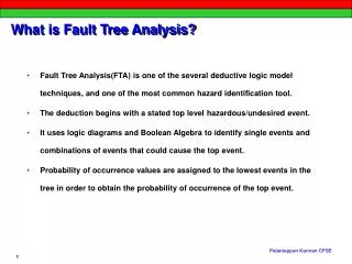
Presentation Transcript
Fault Tree Analysis Part 2: Problem Definition and Heuristic Guidelines for Fault Tree Synthesis
FTA Procedure • Problem Definition • Fault Tree Synthesis • Solution - Minimal Cut Sets • Probability Calculation
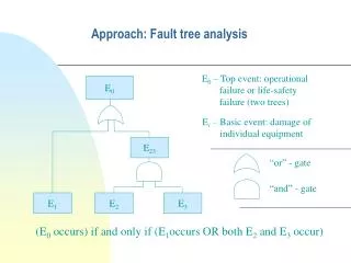
Step 1: PROBLEM DEFINITION • TOP Event • Boundary Conditions - unallowed events (impossible events) - existing events (certain events) - system physical bounds - level of resolution - other assumptions , e. g. Initial conditions.
Step 2: FAULT TREE SYNTHESIS COOLING WATER EMERGENCY HEAD TANK REACTANT X REACTANT Y E M COOLING WATER OUT COOLING WATER IN COOLING WATER SUPPLY PUMP PUMP X
LOSS OF REACTION CONTROL (A+B+C)+(B+D+E)+(B+F).G OR SUPPLY OF REACTANT X STOPS LOSS OF AGITATION LOSS OF COOLING ON JACKET AND OR OR (A+B+C) (B+D+E) (B+F).G PUMP X FAILS OPERATOR ERROR FAILURE OF POWER SUPPLY AGITATOR MECHANICAL FAILURE FAILURE OF WAWER SUPPLY FAILS EMERGENCY SUPPLY FROM HEAD TANK FAILS OR OR C B E G (A+B) (B+F) PUMP X MACHANICAL FAILURE FAILURE OF POWER SUPPLY OPERATOR ERROR FAILURE OF POWER SUPPLY WATER PUMP MECHANICAL FAILURE A B D B F
HEURISTIC GUIDELINES 1) Replace an abstract event by a less abstract event. Loss of Cooling water No Water from Pump 2) Classify an event into more elementary events. Tank Explosion OR Explosion Explosion by by Overfilling Runaway Reaction
HEURISTIC GUIDELINES 3) Identify distinct causes for an event. Runaway Reaction OR Excessive Loss of Feed Cooling 4) Couple trigger event with “no protective action”. Overheating AND Loss of No System Cooling shutdown Water
HEURISTIC GUIDELINES 5) Find cooperative causes for an event. Fire AND Leak of Source of Flammable Fluid Sparks 6) Pinpoint a component failure event. No Cooling Water AND Main Valve Bypass Valve is Closed isn’t Opened Note, 1) - 6) are state-of-system events.
7) Develop a component failure using Fig. 2.22 Component failure (state-of-component event) Command fault Primary failure Secondary failure State-of-system event Figure 2.22. Development of a component failure (state-of-component event).
Example - The Process This example shows how the heuristic guidelines can be used to construct fault trees. In the pumping system shown in the next page, the tank is filled in 10 min and empties in the next 50 minutes; thus, the cycle time is 1 hr. After the switch is closed, the timer is set to open the contacts in 10 min. If the mechanisms fail, then the alarm horn sounds and the operator opens the switch to prevent a tank rupture due to overfilling.
Operator Horn Switch Contacts Power supply Pump Tank Timer Schematic diagram for a pumping system.
Example - The Fault Tree A fault tree with the top event of “tank rupture (at time t)” is shown in the next page. This tree shows which guidelines are used to develop events in the tree.
Operator Failures The operator in this example can be regarded as a system component, and the gate E is developed by using the guidelines of Fig. 2.22. A primary operator failure means that the operator functioning within the design envelope fails to push the panic button when the alarm sounds. The secondary operator failure is, for example, “operator has been killed by a fire when the alarm sounded.” The command fault for the operator is “no alarm sounds.”
Lambert, H. E. , “System Safety Analysis and Fault Tree Analysis,” UCID-16238, 31, May 9, 1973 Expect no miracles; if the “normal” functioning of a component helps to propagate a fault sequence, it must be assumed that the component functions “normally.” Write complete, detailed fault statements. Avoid direct gate-to-gate relationships. Think locally. Always complete the inputs to the gate. Include notes on the side of the fault tree to explain assumptions not explicit in the fault statements. Repeat fault statements on both sides of the transfer symbols.
Example The following figure shows a reaction system in which the temperature increases with the feed rate of flow-controlled stream D. Heat is removed by water circulation through an exchanger. Normal reactor temperature is 200 F, but a catastrophic runaway will start if the reactor temperature reaches 300 F.
Example In view of this situation, • The reactor temperature is monitored; • Rising temperature is alarmed at 225 F (see horn); • An interlock shuts off stream D at 250 F, stopping the reaction (see solenoid and valve A); • The operator can initiate the interlock by pushing the panic button.
Assumptions • Secondary failures are neglected. • The alarm signal always reaches the operator whenever the horn sounds