Download
1 / 25
250 likes | 435 Vues
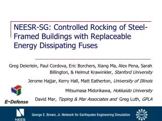
NEESR-SG: Controlled Rocking of Steel-Framed Buildings with Replaceable Energy Dissipating Fuses. Greg Deierlein, Paul Cordova, Eric Borchers, Xiang Ma, Alex Pena, Sarah Billington, & Helmut Krawinkler, Stanford University Jerome Hajjar, Kerry Hall, Matt Eatherton, University of Illinois

E N D
NEESR-SG: Controlled Rocking of Steel-Framed Buildings with Replaceable Energy Dissipating Fuses Greg Deierlein, Paul Cordova, Eric Borchers, Xiang Ma, Alex Pena, Sarah Billington, & Helmut Krawinkler, Stanford University Jerome Hajjar, Kerry Hall, Matt Eatherton, University of Illinois Mitsumasa Midorikawa, Hokkaido University David Mar, Tipping & Mar Associates and Greg Luth, GPLA
Discussion issues • Prototype Building Information • Preliminary E-Defense Test Setup • Testbed Details • Dual versus Single Rocking Frame • List of Other Issues • Schedule and Logistics • Industry Collaboration Opportunities
Summary of Parametric Study Resultsfor Prototype Building α Peak Response Values Hall, K. et al. 2006, Report No. ST-06-01, Dept. of Civil & Environmental Engineering, UIUC * Peak values are the mean values of peak response values from a set of scaled ground motions
Preliminary Design of System Test at E-Defense (2009) • Large (2/3 scale) frame assembly • Validation of dynamic response and simulation • Proof-of-Concept • construction details • re-centering behavior • fuse replacement • Collaboration & Payload Projects
Similitude Model and Assumptions • Proc. 1 Mass density ratio = 1 • Time distorted • Proc. 2 Time and strain rate ratio = 1 • Mass ratio relatively large • Proc. 3 Acceleration ratio = 1, mass ratio reasonably small, time not too distorted • Preferred option
Inferred Demand Parameters for Specimen Comparison of Floor Mass Unit: metric ton. 1 ton = 9.8 kN = 2.2 kips • Testbed floor mass: 60 ~ 100 ton Inferred Force Demands for 4-story Specimen
Unit: mm. 1000 mm = 3.28 ft Basis Parameters of Specimen Approximate Member Sizes • Dimension scale lr = 0.68 • Member size determined by scaling from prototype • Shown in red circle are displacement range for each joints
Testbed Details • New load cell configuration • Horizontal cross-bracing between testbed frames • Attachment to frame specimen • Roller detail • Pin detail with exterior columns
Old versus New Load Cell Configuration Center Load Cells (new) Side Load Cells (old)
Horizontal Cross-bracing members Interfere with frame specimen
Horizontal Cross-bracing members Solution under consideration Cross beams to connect the two testbed frames Cables to tie together the white and blue beams
ABAQUS Modeling of Fuse Similar Deformation Mode
Load-Deformation Curves of a Case Test ABAQUS Analysis 10~20% higher loads
List of Other issues • Design anchoring specimens to the table • Use steel or concrete for base beam? • Resistance capacity of shake table • Available instrumentation • number of channels • type and number of instruments • Ground motion record • what record to use • how it would be scaled • Construction of specimen • how to assemble frame specimen • Construction sequence (Testbed first and then specimen? or sequential installation of testbed 1, specimen, testbed 2)
Schedule and Logistics • Schedule • Spring 2008, UIUC test • Summer 2008, finalization of E-Defense specimen design • Autumn 2008, finalization of instrumentation plan • Winter 2008, E-Defense specimen construction & instrumentation • Spring 2009, E-Defense test • Logistics • Confirmation of student team members and establish contact. (Tokyo Tech: Hirotaka Ando? Kyoto Univ:? E-Defense: ?) • When to send students to E-Defense
Industry Collaboration Industry partners from Japan to participate in design, detailing, and construction (Nippon Steel Corp? Other consultants or fabricators?) In-kind funding for materials (shapes, plate, connectors), fabrication (specimens and load frame components [trough, loading beams, etc.]) Fuse fabrication (same fabricator as specimen?) Supplier of PT cables and anchorages, and contractor for installation (E-Defense staff?) Capabilities for E-Defense staff in steel erection (e.g., bolting of fuses, resolution of fit-up issues) Other issues?