Download
1 / 25
250 likes | 467 Vues
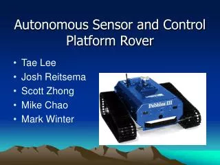
Autonomous Sensor and Control Platform Rover. Tae Lee Josh Reitsema Scott Zhong Mike Chao Mark Winter. Brief Description. An easily extensible autonomous rover platform. Initially equipped with SONAR, IR, and bumper sensors. A camera for remote viewing and control.

E N D
Autonomous Sensor and Control Platform Rover • Tae Lee • Josh Reitsema • Scott Zhong • Mike Chao • Mark Winter
Brief Description • An easily extensible autonomous rover platform. • Initially equipped with SONAR, IR, and bumper sensors. • A camera for remote viewing and control. • Functionally extendable control program makes the rover extremely versatile.
Goals • Central processing and control circuitry. • Control for devices: Motors, SONAR, IR, and bumpers. • Communication with a computer via serial or possibly WIFI for programming and remote control. • Camera mounted on rotating platform, to provide computer controllers with a video display
Extensions • WIFI communication with computer. • DSP for video to heighten the rover’s “senses”
Cost and Returns • Initial costs are low because of the availability of a basic rover platform for prototyping, equipped with motors and sensors. • Given the high versatility of the Autonomous Sensor and Control(ASAC) platform, we can expect high demand from companies requiring an autonomous unit for sensor data collection in inaccessible areas.
Needed Hardware Subsystems • Main Controller Board • Sensor Interface Hardware • Motor Controller Hardware • Communication to Human Interface
Main Controller Board • Based on 2120 board • Motorola 68HC11 processor, Xlinix logic chip, multiple I/O buslines for input to sensors and output to motors • Needs to be programmable in C, C compilier
Other Hardware Systems • Each sensor, video, IR, wheel encoders, etc., needs to be interfaced into the main controller board • Communication will be wi-fi and direct connect • The motors must be set precisely with correct current and voltage
Software Subsystems • Drivers for hardware will be written in Assembly • High level control, i.e. decisions and behavior, will be written in C • Control will be accessed through a graphical user interface
Implementation of Various Subsystems • Chassis • Mainboard • Power • Communications • Sensors
Chassis • Provided with a stripped down vehicle • Frame • 2 X 12V stepper motors • Controlled using a Generic H-Bridge. • Sonar sockets placed around the cart • Possibly implement if time permits.
Mainboard • Using a 68HC11 to process commands • FPGA • Will handle expanded IO to sensors. • Will execute movement commands.
Power • Regulators will provide 3 different voltages. • 12V • Motors • 5V • Motorola 68HC11 • Xilinx FPGA • 3.3V • Communication Module
Communication • Programming handled through a serial cable • Integrate a WiFi module • Lantronix WiPort. • Otherwise fall back to RC or wired communication.
Sensors • Camera will feed data to a monitor • Time permitting data will be transmitted over wireless interface. • Otherwise it will have its own independent transmission (baby monitor). • Hopeful expansion • Integrate existing sonar ports.
Division of labor and responsibilities Scott • Main board and processor • Specification of interface between each different module (WiFi, Sonar, etc) Tae • Main board and processor • Manual editor • Ultrasonic Sensors
Division of labor and responsibilities Mike • WiFi Interface • Control of Rover • Sensor Data Josh • Video Camera Interface and Control • Movement Circuit • Ultrasonic Sensors • High Level Control Software
Division of labor and responsibilities Mark • Test and Document Current Hardware • Drivers • Data Processing Algorithms • Video Interface
Division of labor and responsibilities Everyone • Documentation • User manual • Tech Support • Trips to get food
Considerations • Project to Complex? • Too many peripheral sensors • Do we have enough time to do all this • Is there enough processing power • PCB • Eliminate Noise • Wire wrap problems go away • Ultrasonic Sensors • How many do we need for accuracy • How are we going to connect them • Video Feed • Stand alone unit with no integration • Wi-fi using serial • Is it fast enough
Risks • Do we have what it takes • Knowledge of components • Can we learn really, really fast? • Unexpected Complexities • Bad parts, “what's that smell” during testing • How long to fix the unexpected? • Complications during integration of modules • Use of old motors
Contingency Plan • Make sensor sub-systems very modular • Leave out the flash until the end • Make sure the basics work first • Wired communications • Back up for wi-fi • Order extras if we can • Replace old motors with newer model • Data sheets, Support
Thanks • Questions?