Autonomous Visual Rover Project: Design and Implementation Overview
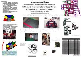
This project aims to develop a low-cost autonomous rover capable of tracking and following a moving object using image processing and color detection. Powered by an Atmel microcontroller, the rover will operate on battery power and maintain a minimum distance of 7 inches from its target. The design will allow for indoor and outdoor functionality with a compact size of 14x7x7 inches. Optional features include autonomous targeting, solar power, and telemetry via Bluetooth. The project leverages CMUcam2+ for image processing and various sensors for navigation and control.

Autonomous Visual Rover Project: Design and Implementation Overview
E N D
Presentation Transcript
Sean Day Diante Reid Liem Huynh Autonomous Visual rover
Project Overview • To create a vehicle that autonomously follows a moving object • To design a low cost, mobile robot that can track objects based on image processing • Implement all of the parts using the Atmel microcontroller • Fire at target object when specified
Requirements • Autonomously track and follow a moving object using color detection • Operate on battery power and not other external source of power • Keep a minimum of 7 inches away from it target at all time. • Operate both indoor and outdoor • Operate for more than one hour on a fully charged battery. • Have a dimension of no more than 14x7x7 inches
Optional Features • Autonomous weapons system • Solar Power • The AVR shall be able to communicate and upload telemetry data to the user via Bluetooth • The AVR shall be able to map its surrounding and navigate to a designated target with GPS.
SensorsManager Guidance, Navigation and Control Environment CMUCam2+ Top Level Diagram Images Centroid and ServoLocation TargetLocation Target Maxbotix LV-EZ2 UltrasonicSignals PWM TargetRange IR Detector On-OffPulses ChassisVelocity Environment Actuators Software Hardware PWM EncoderPatterns
Microcontroller - Arduino • ATMEGA328 • USB Interface • Cross-platform • Easy to program • Open source • Well documented
Printed Circuit Board • PCB123 software • $100 student credit from sunstone • Prototyped on the Arduino board • 2 layer design • Using through hole and surface mount techniques
CMUcam 2+ Vision Sensor Performs image processing duties for AVR Track user defined color blobs at up to 50 Frames Per Second (frame rate depends on resolution and window size settings) Track motion using frame differencing at 26 Frames Per Second Find the centroid of any tracking data Gather mean color and variance data Gather a 28 bin histogram of each color channel Process Horizontally Edge Filtered Images
Image Processing Requirements • Color detection • Motion detection • Flexibility for programming • Ability to distinguish between specified color and other colors in environment • Work efficiently in well lit environment
Image Processing Techniques • Edge Detection • Canny detection • Edges are areas where a jump in intensity from one pixel to the next occurs • Able to reduce the amount of data processed by filtering out useless information
Blob Detection • Middle Mass • Determines if a group of connecting pixels are related to each other by surroundings • Efficient in identifying separate objects in a scene
CMOS vs. CCD Sensor CMOS CCD • Transistor based • Flexible design • Average picture quality • Low power consumption • Low Price • Analog device • Rigid design • Excellent picture quality • Power hungry • Very Expensive
Choosing a Vision System • CMUcam1 • CMUcam2 • CMUcam3 • AVRcam • Logitech QuickCam Orbit AF Webcam + RoboRealm
CMUcam2+ Software • Open Source Programmable • Hybrid Version of C Language • CMUcamGUI
Why CMUcam2+ • Compact Size • Frame Buffering • Affordable price • Flexible • Multiple Servo Control • User Support
Voltage Regulation • All parts on AVR can run off of 5volts DC • Stepping Down 7.4 volt battery • LM317 adjustable regulator
Purpose is to keep AVR within 6 inches of target object Be able to fit on front bumper Will not loose the target object Low power consumption Ultrasonic Sensor Requirements
Maxbotics Ultrasonic Sensor • Maxbotics EZ1 • Will easily fit on bumper • Only draws 2mA of current • Easy to interface
Interfacing the Sensor • Pulse Width Modulation • 147 microseconds/inch • Analog Input • (Vcc/512)/inch
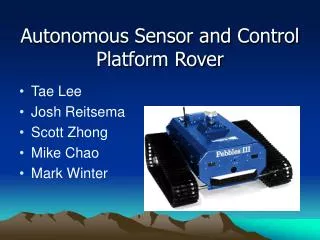
Chassis • RC car from ToysRus • 4 wheels • 2 front turning wheels • 2 rear wheels for going back and forward • 2 DC motors • Roomy
Servos • DC Motors • RC Servos • Stepper Motors
Sensors Manager • getRange() • Returns range from Ultrasonic Sensor in inches • getVelocity() • Returns velocity from IR detector/reflector in inches/seconds • getCentroid() • Returns centroid location of target in x and y format
Sensors Manager • getPan() • Returns location of panning servo • getTilt() • Returns location of tilting servo • getTime() • Returns microprocessor’s time
GNC • Determine velocity using the encoder wheel and IR detector/reflector
GNC • Tracking the target’s centroid 1 44 88
GNC 128, 0° • CMUcam to Body alignment • Body Frame, CMUcam Frame Servo Positions 46, -90° 210, 90° β Offset = 44 sin( β ) Centroid_B = Centroid_C + Offset
Initialization GNC Navigation Flowchart Locate Centroid Centroid < 34 Centroid > 54 ForwardLeft ForwardRight else no Target’s range <=5 inches? Stop Forward Straight yes
GNC Proportional-Derivative Controller P (Range) Input Output + + Plant - Error - D (Velocity) • Variable speed depends on range from target and how fast the AVR is moving • P and D gains need to be tuned • All control process is done through software • Sum of error terms multiplied by the gains translate to voltage to drive the actuators (Error*Range) + (Error*Velocity) = Voltage
Testing • DC Motor/ H-bridge test • Range Finding Test • CMUcam2+ Pan and Tilt Test
Testing • DC Motor/H-Bridge turning wheels test • IR Detector/Reflector test • IR Detector/Reflector encoding wheel test • Chassis/Locomotion test with turning wheels • Locomotion test with IR detector/reflector
Testing • Locomotion test with ultrasonic sensor stationary target • Locomotion test with ultrasonic sensor moving target • Locomotion test with CMUcam2++ with stationary target • Locomotion test with CMUcam2++ with moving target • Locomotion test with all sensors
Progress • Part allocation – 90% • Testing – 10% • Design – 95% • Construction/Prototyping – 20% • Total completed -50%