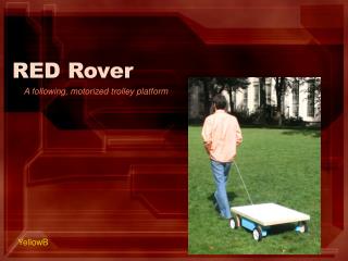
RED ROVER
RED ROVER. Team CPNE Crossen Davis Peter Ramer Nancy Robinson Eric Rodriguez. Red Rover System. Accelerometer. Temperature sensor. LCD. Camera w/ audio. Ultrasonic Transducer (2). Power distributed to all chips. Base Station System. Data Bus Driver. EPROM. CLOCK. MC68HC11.

RED ROVER
E N D
Presentation Transcript
RED ROVER Team CPNE Crossen Davis Peter Ramer Nancy Robinson Eric Rodriguez
Red Rover System Accelerometer Temperature sensor LCD Camera w/ audio Ultrasonic Transducer (2)
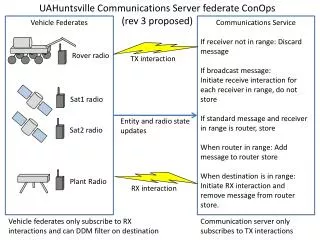
Power distributed to all chips Base Station System Data Bus Driver EPROM CLOCK MC68HC11 Vdd Vss 8 Data Serial Data From Computer CLK Address Bus Driver Reset RAM 8-14 Address Reset Circuit Address Bus Driver Receiver from vehicle Transmitter to Vehicle
Power distributed to all chips / Separate Power for motors Vehicle Processor System Data Bus Driver EPROM CLOCK Vdd MC68HC11 Vss 8 Data Serial Data From Computer Temperature sensor CLK Address Bus Driver Reset RAM 8-14 Address Reset Circuit Accelerometer decoder 4 motors Address Bus Driver H-bridge PWM Ultrasonic Transducer transmitter LCD Ultrasonic Transducerreceiver Receiver from Base station Transmitter to Base station Camera w/ audio
M68HC11 Processor • 8 bit data and 16 bit address • 16 bit timer system • 8 bit pulse accumulator • Real time interrupt • 7 8 bit registers • Interfaces to both local and remote peripherals
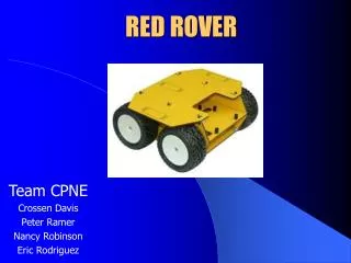
Lynxmotion Robot Chassis 4 7.2V motor chassis Room inside for additional electronics Can carry 5lb load Able to stack decks on top Low or high clearance Decoder Micro-Motor Controller 1 for each motor
Micro Dual Serial Motor Controller Contains 2 parallel H-bridges They allow for bi-directional control of 2 motors 127 different speeds Maximum current 2A PWM frequency of 750Hz • Input is made with 4 bytes of info • Start byte is most significant bit 4 bytes input to SCI
…Input to Serial Control Input • Input of 4 bytes • non-inverted logic • 8 bits at a time, no start bit, 1 stop bit • MSB read first and last bit must be clear • To configure: need to send 3 byte packet Bit 6: = # of motors, so in our case, =1 Bits 0-5: motor #, in our case, 1-4 After configurations set: programming protocol: 4 bytes Bit 7: always 0 Remaining: 0x00 turns off motor 0x7F turns fully on f0 in reverse brakes Bit 0: direction (1 forward, 0 backward) Bits 1-6: motor number Bit 7: always 0
Transceiver • 433Mhz Multi-Channel RS-232 Serial RF Transceiver • 10 selectable channels • Three baud rates: 9600, 19200, and 38400 bps • -104dBm sensitivity
Camera and Audio Miniature and Lightweight 1.2 GHz Needs 8-9V power supply RC connection for receiver Resolution 380 lines Rotates w/ horizontal motor Motor movement controlled by PWM for slow movement and limited angle Connected directly to monitor
Digital Temperature SensorDS18S20 Gives 9 bit centigrade temperature Upper and lower programmable trigger points 1-wire bus/ LSB first -55°C to 125°C Accuracy within .5C Can power from data line or Vcc Data stored in 16-bit sign-extended two’s complement number in its own temperature register DS18S20 Gnd DQ Vdd Vpu Vehicle Microprocessor 4.7k 1-wire bus
Ultrasonic 25kHz Transducers Excited by 25kHz square wave Filters out signals outside 24-26kHz band Transmitter transducer driven by 10 cycle square waves and receiver transducer receives echo Timer on HC11 counts time for the return echo Speed of sound 1100ft/s So object (1100 x t)ft away Vehicle Microprocessor Burst of sound waves to object Transmitter Corresponding echo start Timer Receiver Amplifier stop
Accelerometer Breakout Board - ADXL E8 Series • 2 axis acceleration and tilt sensor • Low power <.6mA • Direct interface to microcontrollers via duty cycle modulation (DCM) • Duty cycle=pulse width/period • DCM measured by counter/timer to determine acceleration • Acceleration = (T1/T2-.5)12.5% Vdd ADXL202E VDD Vdd T2=Rset/125Mohms XA LP Filters HC11 Counter/timer GND YA T2 XP YP T1
LCD 16x4 character display HD44780 parallel interface Uses HD44780U LCD Driver Vehicle Microprocessor LCD Vss Vcc Vee Rs R/W E DB0-7 Vcc
Software Using Tera Term for monitor program User interface programming in C++ Microprocessor data manipulation and peripheral interface in assembly and C++ Considering FPGA programmed using Verilog
Done so far… Most of the processor done and awaiting testing. Will be done with both processor boards with testing by Monday Started ordering parts
Parts list Base Station Processor Board, w/ M68HC11, EPROM, RAM,,… Vehicle Processor Board, w/ same components Pololu Robot Chassis Digital Temperature Sensor Accelerometer 2 Transceivers Graphic LCD Camera w/ audio 2 Ultrasonic Transducers
Division of labor and responsibilities Crossen: Vehicle processor, Code, Chassis & Motors, Temp Sensors Peter: Vehicle processor, Code, LCD, Accelerometer Nancy: Base station, Code, Transducers, User’s Manual Eric: Base station, Code, Transceiver, Video