Rover Chassis
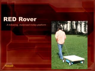
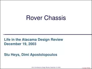
Rover Chassis. Life in the Atacama Design Review December 19, 2003 Stu Heys, Dimi Apostolopoulos. Description and Motivation. A new rover chassis for mobility and science is to replace Hyperion in the upcoming campaigns That is motivated by the need to Accommodate various science instruments

Rover Chassis
E N D
Presentation Transcript
Rover Chassis Life in the Atacama Design ReviewDecember 19, 2003 Stu Heys, Dimi Apostolopoulos Carnegie Mellon
Description and Motivation • A new rover chassis for mobility and science is to replace Hyperion in the upcoming campaigns • That is motivated by the need to • Accommodate various science instruments • Improve mobility especially in inclined terrain • Optimize propulsion subsystem Carnegie Mellon
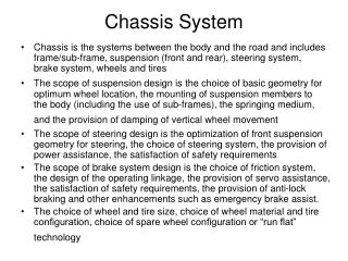
Key Requirements & Design Drivers • Provide unobstructed FOV and necessary actuated motions for science payloads • Modify wheel design to improve terrainability • Increase wheel torque to improve slope climbing • Increase rover speed to decrease traverse times • Eliminate drivetrain hysteresis to improve control • Minimize mechanical complexity. Maintain as much of Hyperion’s design as possible • Design for 150 kg GVW Carnegie Mellon
Building on Hyperion’s Competencies Carnegie Mellon
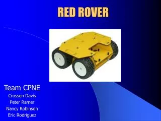
New Rover Configuration Pan and tilt unit base atop forward leaning mast Fluorescence imager location .85m range of motion ~2.3m2 solar array ~.32m3 electronics enclosure roughly equal in volume to Hyperion Drivetrain completely enclosed by axle structure Steer and roll articulation at front and rear Carnegie Mellon
Steering & Articulation Chassis averages as front tire climbs 30cm obstacle Carnegie Mellon
Evaluation of Steering Geometries Carnegie Mellon
Sub panels slide out of frames with integrated electrical connections Panels fold up for easy access to e-box and science instruments Sensor & Solar Panel Configuration Science instruments isolated from vehicle controls Electronics box nestled between frame members Linear table spans frame members, supports fluorescence imager Carnegie Mellon
FEA results for axle Technical Approach • Prototype chassis roll mechanism • Tune-up controller to optimize mobility • Utilize test results to finalize detailed design of axles and pivots • Define volumetric and instrument functional requirements • Finalize sensor placement configuration • Detail design chassis for optimal accommodation of the solar panels, electronics and science instruments • Design mechanism for fluorescence imager and pan/tilt unit • Integrate prototype instrument deployment mechanism on Hyperion Carnegie Mellon
Design & Implementation Issues • Complex Integration • Science payloads (esp. fluorescence imager) • 2+ degree of freedom • Mast (in-house pan & tilt design) • Design for 4+ cameras • Solar panels • Optimized for cell size while avoiding wheel interferences • Plow • Tricky deployment issues Carnegie Mellon