Rolling Chassis Team
Rolling Chassis Team. Todd Anderson Matt Blackwood David Hovater Josh Smith Jessica Yoho. Overview. Formula SAE at a Glance Project Summary Frame Suspension Brakes Steering Seat Uprights Building Parts Lathe Mill Large Band Saw Small Band Saw Composites Important Dates.

Rolling Chassis Team
E N D
Presentation Transcript
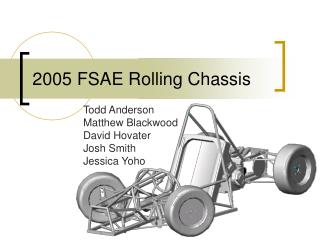
Rolling Chassis Team Todd Anderson Matt Blackwood David Hovater Josh Smith Jessica Yoho
Overview • Formula SAE at a Glance • Project Summary • Frame • Suspension • Brakes • Steering • Seat • Uprights • Building Parts • Lathe • Mill • Large Band Saw • Small Band Saw • Composites • Important Dates
Formula SAE Competition • One of the largest Collegiate competitions • Design, build, and compete with small Formula style cars • 140 Universities from around the world compete in static and dynamic events • Increase awareness for The University of Alabama • Covers many aspects of Engineering • Competition Date: 5/18/2005 – 5/22/2005
Formula SAE • 0-60 in under 4 seconds • Can corner up to 1.5 g’s • Weighs around 500lbs • 70 Hp Engine
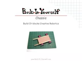
Project Statement • Design, build, and test a rolling chassis for integration with the 2005 UA Formula SAE car design.
2005 Car at a Glance • 66” Wheelbase • 48/46” Front Rear Track • Seating Position under the Main Roll Hoop • Two Pedals • Pull Rod Suspension • Semi Stressed Engine
Frame Objectives • Reduce Weight • Less than 60lbs total weight for the Frame • Use of Thinner Tubing • Increased Driver Room • Increase Torsional Resistance • Reduce Complexity • Integrate Subsystems into Frame • Use of Square Tubing • Partially Stressed Engine • Easier to Build • 4130 Spaceframe
Frame Analysis (Front) • FEA Analysis in ANSYS • Max Deflection: <0.08in • Max Stress <31ksi
Suspension at a Glance • Double A-arms • Low Roll Center • Pull Rod • Vanilla RC Bicycle Shocks • Anti-Sway Bar • Use of Spherical Bearings
A-arm Attachment to Frame Shims 1/4” bolt Front View A-arm Aluminum Bracket Spherical bearing & housing
Spherical Bearings • Mis-Alignment Angle of 24º • Will Be in Housing held in place by a snap ring
Front A-arms Analysis FEA • ANSYS Results • Loaded to Simulate Braking and Cornering • Max Deflection <0.05” • Max Stress <22ksi
Brakes At a Glance • 3 Disc Setup • 2 Outboard Brakes in Front • 1 Inboard in Rear • 9” Diameter Rotors • Dual Piston Calipers • Left Foot Brake setup (Only two Pedals) • Balancing Bar
Brakes • Wilwood PS-1 Calipers • Dual 1.12 inch pistons • 9”Custom Rotors • Dual master cylinders • Balancing bar used to adjust bias PS-1 Caliper Dual MC Balance bar
Steering • Located under Driver’s legs • Ackerman Geometry • 12 ft Turning Radius • Minimal Bump Steer • Two Universal Joints to Route Steering Linkage
Steering Rack Jr. Dragster Steering Rack From Chassis Shop • Track Travel: 3” • Weighs 1.96 lbs • Rack Length is 8.5” • 1.125 Turns Lock to Lock
Seat at a Glance • Carbon Kevlar Composite • Reclined 30º from the Vertical • Legs Elevated 4” • Lateral Support
Front Upright • Brake Caliper Bracket moved to integrate into Steering Attachment • Steel Construction opposed to Aluminum • Similar Weight • Reduced Cost • Easier to Make • Endurance • Rotor Mount integrated into Wheel Studs • Smaller Spindle and Inboard Bearing to take Advantage of Strength of Steel
Front Upright FEA Analysis • ANSYS • Max Deflection <0.003” • Max Stress < 16ksi • Weighs Approximately 2.75lb with Axle and Brake Bracket
Rear Uprights at a Glance • Aluminum 6061-T6 • CNC Design • Minimal Deflection • Lightweight • Taylor Racing Stub Axle
Rear Uprights • Overall Dimensions • Constraints / Loading Conditions • Maximum Deflection is 0.002” • Maximum Stress is 3500 psi
Stub Axle • Stub Axle Assembly will be changed to same model used in 2004 Car • More Expensive but can be covered with new Funds • Much Stronger, more Proven, and Lighter • Manufactured by Taylor Racing
Building Plans • Construction of Rolling Chassis needs to be completed by December 16th • 489 Currently occupying Projects Building • Starting November 11th 1-4pm Weekday Afternoons • Wednesday November 24th – All day
Lathe • Spindle • Housings for Spherical Bearings • Engine Mounts
Mill • Frame Members • Pieces for Jig Table • Assembly Jig for Front Upright • A-arms • Brake Rotor
Large Band Saw • Frame Members • Front Upright Pieces • A-arms
Small Band Saw • A-arm Attachments • Front Upright
TIG Welder • Frame • Frame Jig Table • Front Uprights • A-arms • A-arm mounts to Frame
Other • Bench Grinder • A-arm Attachments • Front Upright • Chop Saw • Frame Members
Composite Step 1: Sand seat to proper dimensions Step 2: Apply Bondo to the entire seat Let seat dry for 24 hours Step 3: Sand down seat to a smooth finish with fine grit sandpaper Step 4: Cut several sheets of Carbon Kevlar fabric to the specified dimensions. Step 5: Lay one sheet of fabric vertically on the seat mold and apply resin. Allow to dry. Step 6: Lay another sheet of fabric horizontally on the seat mold and apply resin. Allow to dry. Repeat as needed. Step 7: Discard foam mold. Before After
Important Dates • November: • 7th Last Autocross of the year in Birmingham • 17th Engine Mounted to Dyno • 24th • Drivetrain Coupling Completed • Composite Process • Build Date in Projects Building • December: • 4th Stock Engine Running • 16th Rolling Chassis Completed • January: • 21st • Running Engine With Restrictor • Pedal Construction • March: • 18th • Driving