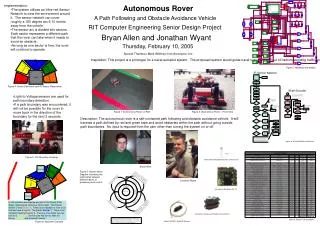
Autonomous Rover: Path Following and Obstacle Avoidance System
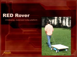
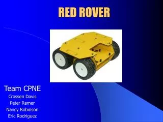
The Autonomous Rover is a self-contained vehicle designed for path following and obstacle avoidance using an Infra-red Sensor Network that covers a 180-degree arc within 6-10 inches. The system is divided into sectors, allowing the rover to navigate by selecting a free path to avoid obstacles. It operates without user input apart from turning the device on or off, making it suitable for tasks like guiding naval vessels in crowded or shallow harbor areas. This prototype showcases advanced engineering principles in automated navigation.

Autonomous Rover: Path Following and Obstacle Avoidance System
E N D
Presentation Transcript
Sector 1 Sector 1 Sector 2 Sector 2 Sector 3 Sector 3 Rover Rover IR1 IR1 IR2 IR2 IR4 IR3 IR3 IR4 Sector 5 Sector 5 Sector 4 Sector 4 IR5 IR6 IR6 IR5 IR7 IR8 IR8 IR7 Obstacle Obstacle • Implementation: • The system utilizes an Infra-red Sensor Network to view the environment around it. The sensor network can cover roughly a 180 degree arc 6-10 inches away from the vehicle. • The sensor arc is divided into sectors. Each sector represents a different path that the rover can take when it needs to avoid an obstacle. • As long as one sector is free, the rover will continue to operate. Autonomous Rover A Path Following and Obstacle Avoidance Vehicle RIT Computer Engineering Senior Design Project Bryan Allen and Jonathan Wyant Thursday, February 10, 2005 Special Thanks to Mark Whitney from Acroname, Inc. Inspiration: This project is a prototype for a naval autopilot system. The proposed system would guide naval vessels in and out of harbors avoiding traffic and shallow areas. Figure 7:Hardware Schematic Figure 4: Sector Definitions and IR Sensor Placements • Light-to-Voltage sensors are used for path boundary detection. • If a path boundary was encountered, it will not be possible for the rover to move back in the direction of the boundary for the next 3 seconds. Figure 1: Autonomous Rover on Path Figure 2: Autonomous Rover – Front View Description: The autonomous rover is a self-contained path following and obstacle avoidance vehicle. It will traverse a path defined by red and green tape and avoid obstacles within the path without going outside path boundaries. No input is required from the user other than turning the system on or off. Figure 8: TEA VM Software Flowcharts Figure 5: LTV Mounting Housings Texas Advanced OptoElectronic’s LTV Sensors Bryan Allen Figure 3: System Block Diagram illustrating the relationship between different layers of processing and control. Jonathan Wyant Acroname’s Brainstem GP 1.0 In this situation we assume we just hit the Green Path Edge, meaning we cannot go to the right. This blocks Sector 3 and Sector 5. There is an obstacle in front of us that we have to avoid. This blocks Sector 1. There is an obstacle blocking Sector 4. The only free sector we can turn to is Sector 2. So the rover will turn so that it is facing Sector 2 and proceed forward. Acroname’s Continuous Rotation Servo Motors Figure 8: Project Cost Breakdown Figure 6: Algorithm Example Sharp’s GP2D15 Digital IR Sensors