Clamper Circuits for Electronic Protection
Learn about clamper circuits, their working principles, and applications in protecting sensitive electronic circuits. Get insights into maximum positive and negative voltages, signal shifting, and DC voltage addition.

Clamper Circuits for Electronic Protection
E N D
Presentation Transcript
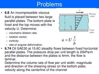
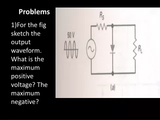
Problems 1)For the fig sketch the output waveform. What is the maximum positive voltage? The maximum negative?
2)For the fig sketch the output waveform. What is the maximum positive voltage? The maximum negative?
3) The diode clamp shown in the figure protects the sensitive circuit. What are the limiting levels?
4)For the fig what is the maximum positive output voltage? Maximum negative output voltage? Sketch output the waveform . If the circuit acts as biased clamp for sine wave input of 20mVwhat is the protection level.
Clamper is a network constructed of a diode, a resister and a capacitor that shifts a waveform to a different level without changing the appearance of the applied signal. • A clamper adds a dc voltage to the signal • A positiveclamper shifts its input waveform in a positive direction, so that it lies above a dc reference voltage. • A negative clamper shifts its input waveform in a negative direction, so that it lies below a dc reference voltage.
Working On the first negative half cycle of the input the diode is turned on. At negative peak capacitor is fully charged to Vp
Beyond negative peak Diode is off RLC is made much larger than the time period of the signal. Stiff Clamper RLC > 100T Due to this reason capacitor remains fully Charged During off time of diode
Clamping is not perfect since diode drops 0.7V.Negative peak have reference level of -0.7V
Application Clampers are used in test equipment radar systems, electronic counter measure systems sonar systems. These are commonly used in analog television receivers to restore the DC component of the video signal.
Application • In measuring nonsinusoidal signals such as square, saw tooth etc .
Problems 1)For the fig sketch the output waveform. What is the maximum positive voltage? The maximum negative?
2)For the fig sketch the output waveform. What is the maximum positive voltage? The maximum negative?
3) Sketch the output waveform of the clamper and final output. What is the dc output voltage with ideal diode? To a second approximation?