Download
1 / 40
420 likes | 661 Vues
Control of Soldering and Thermal Fatigue During Die Casting. Srinath Viswanathan Metals and Ceramics Division Oak Ridge National Laboratory Oak Ridge, TN 37831 NADCA Die Materials Committee Meeting NADCA, Rosemont, Illinois March 6, 2002. Univ. of TN-ORNL Research Team.

E N D
Control of Soldering and Thermal Fatigue During Die Casting Srinath Viswanathan Metals and Ceramics Division Oak Ridge National Laboratory Oak Ridge, TN 37831 NADCA Die Materials Committee Meeting NADCA, Rosemont, Illinois March 6, 2002
Univ. of TN-ORNL Research Team Greg Engleman – Student Narendra Dahotre – Professor/Coatings Craig Blue - Coatings Qingyou Han - Thermodynamics Srinath Viswanathan - PI
Industrial Participants Hayes Lemmerz, Inc. Gibbs Die Casting Ryobi Die Casting TTE Die Casting Metal-Tech
The Program Has Two Goals – Reduce Soldering and Thermal Fatigue • Develop and demonstrate soldering-resistant coatings, using • Room-temperature spray process • high-density infrared (HDI) processing • Develop surface treatments to prevent heat checking, using • surface hardening using HDI • Combine coating and surface hardening.
HDI Cermet Coatings Overcome Spalling Due to Thermal Expansion Mismatch • Coatings deposited by physical vapor deposition spall due to the large difference in thermal expansion between the ceramic coating and the metal substrate. • Cermet coatings offer the solder resistance of ceramics with the stress accommodating properties of metals • ceramic+metal binder powders sprayed on at room-temperature and fused by HDI processing • binder is metallurgically bonded to substrate
Surface Hardening Provides Resistance to Yielding/Plasticity and Prevents Thermal Fatigue • The onset of thermal fatigue is due to plasticity due to yielding during thermal cycling, leading to crack nucleation. • HDI process can rapidly heat the surface and harden to a depth of 0.5 mm • surface hardness can approach 60 Rc • substrate hardness/toughness is unchanged
Preliminary Tests Were Conducted at TTE Casting Technologies • Cr2C3 particles with Ni-based binder were fused on H-13 pins. • Lifetime of coated core pins was extended 2 to 3 times over that of uncoated pins. • Failure of the core-pins was primarily due to soldering. • aluminum reacted with Ni and with Fe that diffused/was mixed into the matrix.
Results of Preliminary Tests Provided Approach for Current Project • A study of the soldering mechanism was conducted using thermodynamic analysis of aluminum-iron system. • Criteria to prevent aluminum attack were established. • The approach will be used to design a solder-resistant binder system (ceramic particles are not attacked by aluminum). • Current project will aim 10x increase of life over uncoated pins.
In the First Year, Coating Systems and Surface Hardening Will be Evaluated • Evaluation of coating systems • thermal expansion characteristics and thermodynamic models will be used to select a suitable binder system • core pins will be tested in laboratory dip test • pins will be characterized and evaluated • Surface hardening will be evaluated • Samples will be tested in lab-scale thermal fatigue simulator
Year Two Will Involve Optimization and Selection of Binder and Industrial Trials • Refine and improve coating systems in a controlled and systematic manner. • Conduct soldering tests in ORNL research die casting machine. • Initiate industrial trials of coated core pins and surface hardened inserts. • Select coatings for industrial application and develop guidelines for die life extension. • optimize thermodynamic and transport models • develop soldering criteria
Final Year Will Involve Extensive Field Testing and Development of Guidelines for Use of Technology • Core pins and inserts will be evaluated at industrial partner facilities for performance, repair, and reuse. • Guidelines and procedures will be developed for coating and surface hardening. • Guidelines will be developed for industrial use of coated and hardened core pins and inserts. • Final report and papers in Transactions.
Properties of the Plasma Radiant Source • Single source is 300,000 watts. • Radiant output is short wavelength, 0.2 – 1.4 microns. • Wavelength constant and independent of power level and anode/cathode wear. • Lamp can run form 2% to 100% of available radiant output. • Can change power levels in less than 20 milliseconds. • Converts electrical into radiant energy in excess of 55% efficiency. • Power can be delivered in a scan mode as wide as 35 cm, presently. • Reflector design can allow for area heating. • Three separate plasma heads are available at ORNL, 10, 20 and 35 cm arcs.
Advantages of HDI Processing Are Low Cost, Selective Application, and Ease of Repair • Coatings are inexpensive to produce. • Process is fast as plasma source is a line source and scan at widths as large as 35 cm. • Both coating and surface hardening can be applied selectively and repeated to increase die life.
High Density Infrared Transient-Liquid-Phase Coating Above, cross-section of chromium carbide/Ni-P cermet directly to a 4340 steel substrate and the associated hardness profile.
HDI Coating of Steel Components Large chain parts coated with tungsten carbide/nickel binder.
A Number of ApplicationsHave Been Demonstrated • Fusing of thermal sprayed coatings. • Fusing of powder coatings. • Fusing of ceramic coatings. • Surface alloying. • Sheet fabrication. • High temperature testing. • Hardening of steel. • Post processing of cold spray specimens. • Paint Stripping • Decontamination, concrete powdering or bacteria kill.
Soldering is a Significant Problem in Aluminum Alloy Die Casting • Soldering is a reaction between the aluminum alloy and the die steel. • A layer of iron-aluminum intermetallics are formed at the surface upon soldering. • Soldering causes the casting to stick to the die, resulting in damage to the die and in poor surface quality of the die casting.
A Study Was Conducted to Explain the Mechanism of Soldering • The goal of the study was to answer the following questions: • When does soldering occur? • What does the formation of intermetallics on the surface indicate? • How does the casting solder (join) to the die? • What determines the strength of the bond?
Liquid Phase Occurs Above 655°C forAl>40 wt% in Al-Fe Phase Diagram Fe2Al5 FeAl2 FeAl3 FeAl 655°C
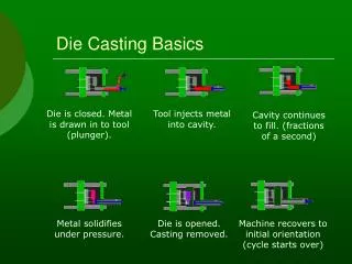
Dipping Tests Were Carried Out at Temperatures Above and Below 655˚C TD = Die Surface Temperature TL = Melt Temperature, 680˚C • Dipping Test: For TD>TL , the sample was repeatedly dipped in aluminum melt to maintain the surface at the test temperature for 1 to 6 minutes. • Dipping-Coating Test: For TD<TL , the sample was dipped in the melt and transferred to a furnace at the test temperature as soon as the surface reached the test temperature.
Soldering Occurred Only When the Surface Temperature Was Above 655˚C
The Steel/Aluminum Interface Exhibited Three Distinct Characteristics • When soldering occurred, a metallurgical bond was formed between the steel and the aluminum, forming phases predicted by the phase diagram. • The absence of soldering was indicated by a separation of the aluminum and the steel, i.e. the presence of an air gap. • In some cases, intermetallic phases were found on the steel even in the absence of a metallurgical bond.
Soldering is Characterized by the Formation of a Metallurgical Bond This type of interface was found in all samples tested at temperatures higher than 655 °C.
The Absence of Soldering is Characterized by the Presence of an Air Gap This type of interface was found in all samples tested at temperatures below 655 °C.
In Some Cases Intermetallic Phases Were Found Even in the Absence of a Bond
The Requirement for Die Soldering is the Formation of a Liquid Eutectic Phase • Aluminum reacts with steel to form an aluminum rich phase and intermetallics. • If the aluminum concentration at the surface is sufficiently high, a liquid iron-aluminum eutectic phase occurs at the die surface - this only occurs if the surface temperature of the die is higher than a critical temperature, TC. • On solidification, this liquid phase links with the casting to cause soldering (metallugical bond).
The Aluminum Composition at the Surface of the Soldered Layer Is about 98wt% The eutectic phase is liquid at the test temperatures when soldering occurred
Liquid Phase Occurs Above 655°C forAl>40 wt% in Al-Fe Phase Diagram Fe2Al5 FeAl2 FeAl3 FeAl 655°C
Soldering Occurs Due to the Presence of Liquid at the Die Surface Reaction between Al and Fe forms intermetalics and an Al rich phase. The Al rich phase is a liquid phase when TD >TC. During solidification this liquid grows to link the casting with the die
Pores Were Observed in the Soldered Region Indicating the Likelihood of Liquid Formation
The Prediction of a Critical Temperature is More Complicated for 380 Alloy Liquidus Temp = 575˚C
A Number of Factors Complicate the Analysis of the Results for 380 Alloy • By analogy with the iron-aluminum system, the critical temperature should be the solidus temperature of the reaction product of 380 alloy and iron. • However, the actual temperature may be between the solidus and liquidus temperatures, as a critical liquid fraction may be necessary. • Dendrite coherency could affect contact between the die and the alloy and thereby affect soldering. • The test must be repeated under actual die casting conditions for the results to be conclusive.
Conclusions • Soldering occurs when the die surface exceeds a soldering critical temperature (655 °C for the Al-Fe system). • The presence of intermetallics is only an indication of a reaction between aluminum and steel, not an indication of the formation of a bond. • When soldering occurs, the metallographic evidence indicates that a liquid eutectic phase was present at the die surface, which then glued the casting to the die. • The strength of the bond depends on the area over which the bond formed, i.e, the local liquid fraction which depends on temperature and composition.
A Soldering Mechanism May Be Postulated by Considering the Thermodynamic Equilibriaof the Die-Melt System The analysis considers that • Soldering is the result of reaction between the aluminum alloy and the die surface. • The reaction product must be liquid for soldering to occur. • When sufficient liquid is present, a strong joint can form between the die and casting on solidification. • Under the above conditions, the (critical) temperature above which liquid can form is given by the solidus temperature in a vertical section of the multicomponent phase diagram (Al-Fe-Si-Cu-Mg system).