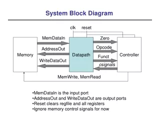
Download
1 / 11
1.1k likes | 3.06k Vues
Power System 1 EEE 3231 One line Diagram, Impedance and Reactance Diagram and Per unit concept. Kazi Md. Shahiduzzamna , EEE, NUB. Outline of this chapter. The One-line Diagram The Impedance and Reactance Diagram The per unit concept and its advantages Base selection. One line diagram.

E N D
Power System 1EEE 3231One line Diagram, Impedance and Reactance Diagram and Per unit concept Kazi Md. Shahiduzzamna, EEE, NUB
Outline of this chapter • The One-line Diagram • The Impedance and Reactance Diagram • The per unit concept and its advantages • Base selection
One line diagram Definition: Often any diagram is simplified by omitting the completed circuit through the neutral and by indicating the component parts by standard symbols rather than by their equivalent circuits. Such a simplified diagram of an electric system is called a one-line diagram.
Example of one line diagram: #1 Generator-20,000 kva, 6.6 kv, X" = 0.655 ohms #2 Generator-10,000 kva, 6.6 kv, X" = 1.31 ohms #3 Generator-30,000 kva, 3.81 kv, XI! = 0.1452 ohrns T l and T 2 -each transformer in each 3-phase bank-10,000 kva, 3.81-38.1 kv, X = 14.52 ohms referred to the high-tension side Reactance of the transmission line = 17.4 ohms Load A = 15,000 kw, 6.6 kv, pJ. = 0.9 lag Load B = 30,000 kw, 3.81 kv, pJ. = 0.9 lag
The Impedance and Reactance Diagrams Definition: When the components of the one line diagram is represented by there corresponding impedance and reactance is known as Impedance and Reactance Diagram of that one line diagram. • Need for The Impedance and Reactance Diagrams: • To calculate the performance of a system under load conditions • To calculate the performance of a system upon the occurrence of a short circuit • Point should be noted that The impedance diagram does not include the • current-limiting impedances shown in the one-line diagram.
The Impedance and Reactance Diagram of the given example of one line diagram is shown below: • Point should be noted • As the magnetizing current of a transformer is usually insignificant compared • to the full-load current, the shunt admittance is usually omitted in the • equivalent circuit of the transformer. • the inductive reactance of a system is much larger than its resistance. So resistance is • omitted from the impedance diagram.
So the impedance diagram is reduce to the following figure where only reactance is existed, This figure is called reactance diagram of the system.
Per Unit Concept: • The per-unit value of any quantity is defined as the ratio of the quantity to its base value • expressed as a decimal. • The ratio in per cent is 100 times the value in per unit. • The per-unit method has an advantage over the per cent method because the product of • two quantities expressed in per unit is expressed in per unit itself, but the product of two • quantities expressed in per cent must be divided by 100 to obtain the result in per cent. • Important points regarding Per unit Quantity: • three-phase circuits are solved as a single line with a neutral return, the bases for • quantities in the impedance diagram are kVAper phase and kV from line to neutral. • For single-phase systems, or three-phase systems where the term current refers to • line current, the term voltage refers to voltage to neutral, and the term kVArefers to kVA • per phase. • But Data are usually given as total three-phase kVAand line-to-line kV. • So The base voltage to neutral is the base voltage from line to line divided by √3. • And the per-unit value of the kVAper phase on the kVA-per-phase base is the per-unit • value of the three-phase kVAon the three-phase kVA base divided by three .
Formulas related various Quantities: For phase base voltage and single phase base kVA. For line to line base voltage and total three phase base kVA.
to change from per-unit impedance on a given base to per- unit impedance on a newbase, the following formula applies: • The Advantages of Per-unit Computations: • Manufacturers usually specify the impedance of a piece of apparatus • in per cent or per unit on the base of the name-plate rating. • The per-unit impedances of machines of the same type and widely • different rating usually lie within a narrowrange, although the ohmic values differ • materially for machines of different ratings. • The way in which transformers are connected in three-phase circuits does not affect • the per-unit impedances of the equivalent circuit. Example related this topics are 6.10 and 6.11 from the book and 8.2 in the soft copy of the book.
Reference Book • Elements of Power System Analysis by Willaim D. Stevenson, Jr.