Timing Counter
Timing Counter. Alessandro M. Baldini PSI July 16th 2002. The CORTES facility. C1. A high resolution (0.1÷1.0 mm) cosmic ray tracking system for detector studies based on the micro-strip gas chamber (MSGC) system. 8 chambers 4 x-view, 4 u-view (5.7° stereo)

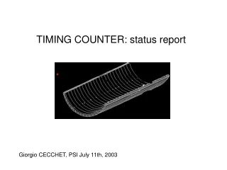
Timing Counter
E N D
Presentation Transcript
Timing Counter Alessandro M. Baldini PSI July 16th 2002
The CORTES facility C1 A high resolution(0.1÷1.0 mm) cosmic ray tracking system for detector studies based on the micro-strip gas chamber (MSGC) system • 8 chambers • 4 x-view, 4 u-view(5.7° stereo) • 512 strips, 3 mm gap, 200 mm pitch • 10.2 x 10.2 cm² sensitive area • average cluster size ~ 3 • ~ 35 m in case of vertical muons • 4cm spacing + 20 cm for test detector • Trigger by scintillators C1,C2 • size = 12 x 12 x 2 cm³, distance = 44 cm • cos > 0.95, 0.05 sr • trigger rate ~ 0.1 Hz • material thickness ~ 0.5 ÷ 1.0 X • -cut to minimise Multiple Scattering effects x-view u-view test counter C2 z y
Operating MSGC’s • Gas mixture: Ne (50%)-Ethane(50%) • (dI/dx 7e/mm for m.i.p. at s.t.p.) • operating voltages: • S/N ~ 30 at Landau peak • Gain ~ 1800 • e > 99% Current gain at b-source proportional regime Many thanks to MSGC people: R.Bellazzini, A.Brez, G.Gariano, L.Latronico, N.Lumb, G.Spandre
The DAQ system VME crate • Front-end • Anode charge signals undergo: • pre-amplification • shaping • peak sampling • multiplexing • accomplished by PREMUX chips • On-line • A VME system based on: • CPU FIC 8251 • SDR-Sequencer • Sirocco Flash-ADC’s • driven by a fast Trigger card • Read-out and analysis • Data sent via TCP-IP to a PC for • event building • data write-out • histogram display Ethernet to PC to J2 PREMUX VIDEO from PREMUX analog Power supply signals from test detector Trigger card from trigger scintillators HOLD to J1 PREMUX
Tracking performances • Independent fit of • x and u-views planes • Plane intersection • cosmic ray track • Track intercept with the • detector plane • hit point • Position resolution: • (limited by stereo angle) z y x effects of Multiple Scattering on soft muons
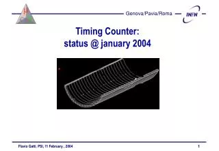
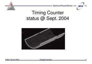
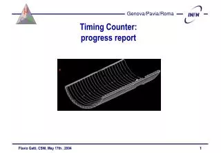
Timing Counter test • Prototype counter assembled with : • BC-404 100x5x1 cm³ • fish-tail light-guides • PMT Philips XP2020/UR, 2” and HAMAMATSU 5946 (1.5”) • T1,T2 (transit time spread = 470 ps FWHM) • Scintillation counter aligned along y-axis • (s = 1 mm) • Time reference provided byT3,T4 • (BC-404, 5x5x1 cm³)
Front-end & digitizers Cross talk in the final electronics? • DAQ electronics consisting in: • NIM LeCroy 623B discriminators driven by PMT anode pulses • CAEN V488AS TDC’s (16 ps least count) operated in Common-Stop mode (C1-C2) • CAEN V465 ADC’s integrating PMT last dynode pulse • VME DAQ system (see above) • Cross-talk TDC cross talk on adjacent channels TDC Stop driven by T3 T4 deviations due todiscriminator cross-talk • Either discriminator input delayed by 10 ns • Use of “far” TDC channels on the same board
TDC calibration • TDC least count • Use of a calibrated pulser with delayable outputs • 1 TDC ch. = 16 pson average • Calibration needed for individual TDC channels (QAC gain variation~ 2% found)
Off-line corrections • event position Use of ab-source ( ) along the counter to determine the effective light speed v = (15.7 ± 0.3) cm/ns average value Sizeable deviationsfrom linearityat counter-ends (direct photon collection, no reflection on walls) Also minor local effects (due to wrapping) are present need to account for variations of light speed along the counter: v=v(y) Can be measured for each counter y (cm) y (cm)
Off-line corrections (cont.) • time-walk measured TDC time measured ADC charge ~ 600 ps walk along the Landau spectrum Both light speed and time walk are determined by an iterative procedure
Timing resolution Two independent estimates of timing resolution • Weighted average Absolute time computed from independent PMT estimates Reference resolution needs to be unfolded from PMT time distribution from rms of (T3-T4)/2 distribution • (T1 - T2)/2 • independent of reference counter
Results We obtain not reliable because of discriminator cross-talk almost independent of muon passage along the counter (although depend on the number of photoelectrons) provides similar results
Do we need precise position determination? Time measurement of both PMT are affected by position error But are anti-correlated if T= T would be independent of y affected by cross-talk • Use of data sample with y-position extracted from with (from positron track fit extrapolation to the TC) • Given y, obtain from previous formulae (~1s larger than non-smeared value)
Hit point on TC difference of MonteCarlo generated point versus track fitting extrapolation track fitting provides a good determination of the TC hit point
Further checks d = 0 • Resolutionvs.number of photoelectrons • Different slant angles to vary the muon path inside the counter • in agreement with photoelectron statistics • Test counter with differentPMTs • Use of new fine-mesh Hamamatsu PMTs • (20 stages, Ø = 1.5 ”, time jitter =470 psFWHM) • data analysis in progress s = 65 ps d = 48.5º s = 55 ps
MC studies • Timing efficiency • 60 ps for E 2 MeV • mainly dominated by photoelectron statistics • E > 5 MeV energy deposit on adjacent • f-cells to achieve100 ps FWHMresolution use of more than 2 PMT’s need to know T(E,x,z) • Trigger efficiency • Use of hit z-cells and f-cells to determine initial positron direction • correlation with max. charge PMT in LiXe calorimeter (providing g direction) • Yet to be studied: use of Q1/Q2 (instead of z-cells layer or in addition: pattern recognition) to determine the z-position e+
TC occupancy Average hit rate 1 KHz/cm²with Global positron rate 5 MHz Distribution - uniform in φ (from axial symmetry) - peaked at higher z (due to positron hitting TC after their 2nd turn)
Efficiencies • Timing efficiency evaluated for different configurations: • 1cm thick inner layer, 2 cm thick outer layer • e(DE>5 MeV) = 85 % • (mainly due to e+ interaction in the inner layer) • e(trigger) = 96.8 % • 0.5 cm thick inner layer, same thickness for outer • e(DE>5 MeV) = 93.6 % • e(trigger) = 97.4 % • reversed layers • e(DE>5 MeV) = 97.5 % • e(trigger) = 75.4 % • ( many events with no hit on z-sliced layer) • unavailable provided one uses Q1/Q2 to determine z
Calibrations(ideas) • On-line: ~2 ns (trigger) ==> LASER system needed also for gain calibration and for monitoring the PMTs • Off-line: relative scintillator calibration by using the 5 MHz positrons: the uncertainty in the distance from one counter to another should be of the order of ~mm => t ~ 10 ps. There are however LASERs with a stability in the time-jitter between the laser pretrigger and the light pulse better than 10 ps. HAMAMATSU PLP-02, 410 nm, low intensity (we have it in Pisa). • Relative timing positron-photon by changing the trigger conditions and using radiative decays