Optimal ADC Design: Insights into Incremental Data Converters
This document explores optimal designs for Analog-to-Digital Converters (ADCs), focusing on incremental data converters (IDCs). It covers application requirements such as high resolution, speed, low power consumption, and environmental insensitivity. The paper discusses the characteristics and classifications of different ADC architectures, along with the evolution of incremental converters since their introduction by Plassche in 1978. Design examples enhance understanding of conversion methods and propose extensions to improve resolution and performance in ADC applications.

Optimal ADC Design: Insights into Incremental Data Converters
E N D
Presentation Transcript
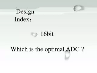
Design Index: 16bit Which is the optimal ADC ?
Incremental Data Converter Date:2013.03.30 • Reporter: SihaiChen TJIC Design Center Battery Management
Introduction 1 Incremental data converter 2 Extensions of First-order Converter 3 Properties of IDC 4 Design Example 5 Contents
Introduction ADC is extensively used. Table 1.1 A/D converter requirements of different applications
Introduction • Application requirements: • high resolution • high speed • simple hardware • low power- and area-consumption • insensitivity of environmental effects • High resolution limitations • analog elements matching • switching-noise
Introduction Table 1.2 Classification of different A/D converter architecture
Introduction • Characteristics of IDC • Converter speed to resolution • Insensitivity of analog elements matching • High resolution • Low~Med bandwidth • Various architectures to make trade-off • Good performance for dc measurements • sensitive to offset, linearity, stability
Incremental Data Converter • 1978, Plassche introduced the structure of first-order incremental data converter for the first time. • 1985, Robert and Valencic introduced a similar structure with more theoretical details in a low-voltage CMOS environment, naming the converter “incremental A/D converter”. • 2004, Markus introduced the modified IDC, and clearly explained the theory and applications of IDC, naming “incremental ΔΣ converter”.
Incremental Data Converter • First-order incremental A/D converter • A hybrid between dual-slope converter and ΔΣ one Figure2.1 Block diagram of the Dual-Slope converter
Incremental Data Converter • First-order incremental A/D converter • A hybrid between dual-slope converter and ΔΣ one Figure2.2 Block diagram of the first-order ΔΣconverter
Incremental Data Converter • First-order incremental A/D converter • A hybrid between dual-slope converter and ΔΣ one Figure2.3 Block diagram of the Dual-Slope converter
Incremental Data Converter • How dual-slope A/D works Two-cycle mode: First-cycle Second-cycle So, there is Question1:How to enhance the resolution of Dual-slope A/D converter?(Clue: ε=?) Note:
Incremental Data Converter • How First-order IDC works At the (N+1)thsampling, Obviously, After , (*) Vin∈(0, Vref), -Vref=0; Vin∈(-Vref,Vref), -Vref= -VrefTo be easily understand, -Vref=0.
Incremental Data Converter • In an ideal A/D converter, • Rearranging Eq.(*), • That is, Question2:How to enhance the resolution of incremental A/D converter? Conclusion:
Incremental Data Converter • For the Bipolar operation, (Vin∈(-Vref,Vref),-Vref= -Vref) • after N cycles, • and ,
Extensions of First-order Converter • The key requirements of extensions: • Fast • High resolution • Actually, it means: (3-1)
Extensions of First-order Converter • Depending on the Eq.(3-1), • α=1, β>0,b>0; • Refining the Quantization Noise (or extended counting conversion) • 0<α< 1, β=0,b=0; • Different Architecture • High-order Modulators
Extensions of First-order Converter • Refining the Quantization Noise • First-order IDC • Refine the residual signal High nbitbit Low nRbit error
Extensions of First-order Converter • Optimal Architecture First-order IDC(3~5bit) + Cyclic(8~10bit)
Extensions of First-order Converter • Optimal Architecture First-order IDC(3~5bit) + Cyclic(8~10bit)
Extensions of First-order Converter • Other Architectures • Multi-bit ADC Refine the quantization in every cycle • Two-steps algorithmic conversion First step: MSB nbit/2 Second step: LSB nbit/2 Total cycles:
Extensions of First-order Converter • Refine the Quantization Noise • First-order IDC • CIFF High-order IDC • Dual-slope converter • Single-slope converter • Cyclic converter • SAR converter • Flash(Pipeline) converter
Extensions of First-order Converter • Refine the Quantization Noise
Extensions of First-order Converter • Different Architecture • MASH(multi-stage noise shaping)
Extensions of First-order Converter • High-order Modulator • To be easily understand, here is a simple architecture. • Low-distortion CIFF second-order IDC
Extensions of First-order Converter • How it works Given the reset signal, V1[0]= V2[0]=0. Time-Domain Z-Domain
Extensions of First-order Converter • How it works • Vinis a constant, • That is,
Extensions of First-order Converter • How it works • The bondage of Vin is ±Vmax , so the Vlsb: • Rearranging,
Extensions of First-order Converter • High-order Modulators • Where La is the order, generally La ≤ 3.
Extensions of First-order Converter • Depending on the Eq. • nbit=16, Umax=0.5, l=2 • N=92 • Actually, Nactual>>N=92
Properties of IDC • “Dead-Zones” • Vmax • Stability • Offset • Line frequency noise • Decimation filter
Properties of IDC • “Dead-Zones” • Vmax
Properties of IDC • Stability* • The higher the order is, the more instability the modulator is. • There is few paper discussing about the stability of modulator, especially incremental ΔΣ modulator, which is extremely significant. • Generally, scaling of the coefficients makes sure that the modulator is stable.
Properties of IDC • Offset • Extremely sensitive to offset • Voffsetremains constant, but Vinj is difficult to evaluate. • Methods • Auto-zeroing • Chopping • CDS • Fractal sequencing
Properties of IDC • Line frequency noise • S/H and the error of S/H • Periodic noise • Decimation filter • CoI filter • Sinc filter • Optimal filter Canceling periodic noise
Design Example • Design index • 12bit • Vin∈[-0.3,5] • VDD=5V • Cycles<1000 • Optimal preferences • Architecture: low-distortion CIFF second-order 1-bit modulator • Bipolar input • SC fully-differential circuits • Fractal sequencing • VDD=5V • Vcm=2.5V • >13bit • Vin+ ∈ [1.175, 3.825] • Vref=5, -Vref=0 • Scaling of coefficients
Design Example • Depending on the preferences: • Cycles: N=256 • Output swing of OTA: 0.3~4.7V, the key limitation of stable.
Design Example • Model of second-order modulator:
Design Example • Architecture circuits
Design Example • Simulate results: offset=0
Design Example • Simulate results: offset=10mV
Thank you for your attentions. The End