
Magnetic Circuits and Materials in Electrical Machines
Learn about magnetic circuits, generators, magnetic materials, and their properties in electrical machines. Explore the laws governing energy conversion and the principles of magnetic fields.

Magnetic Circuits and Materials in Electrical Machines
E N D
Presentation Transcript
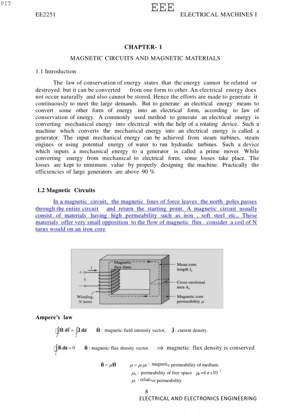
PIT EEE EE2251 ELECTRICAL MACHINES I CHAPTER- 1 MAGNETIC CIRCUITS AND MAGNETIC MATERIALS 1.1 Introduction The law of conservation of energy states that the energy cannot be related or destroyed but it can be converted from one form to other. An electrical energy does not occur naturally and also cannot be stored. Hence the efforts are made to generate it continuouslytomeetthelargedemands. Buttogenerate anelectrical energy meanstoconvert some other form of energy into an electrical form, according to law ofconservationofenergy. Acommonly usedmethod togenerate anelectrical energy isconverting mechanicalenergy intoelectrical withthehelpofarotating device. Suchamachine which converts the mechanicalenergy into anelectrical energy iscalled agenerator. The input mechanicalenergy canbeachieved from steam turbines, steamengines orusing potential energy ofwater torun hydraulic turbines. Such adevicewhich inputs a mechanicalenergy to a generator is called a prime mover. Whileconverting energy from mechanicalto electrical form, some losses take place. Thelosses arekepttominimum value byproperly designing themachine. Practically theefficienciesoflargegenerators areabove90% 1.2 Magnetic Circuits In a magnetic circuit, the magnetic lines of force leaves the north poles passes through the entire circuit and return the starting point. A magnetic circuit usually consist of materials having high permeabilitysuch as iron , soft steel etc., These materials offer very small opposition to the flow of magnetic flux . consider a coil of N turns would on an iron core Ampere’s law . :m . H agnetic field intensity vector, J : current density. Hdl Jda C S . magnetic flux density is conserved 0 B : magnetic flux density vector. B da S r 0:magneti B H c permeability of medium. 7 0:permeabilityoffreespace 0=4 10 r : relati ve permeability 8 ELECTRICAL AND ELECTRONICS ENGINEERING
PIT EEE EE2251 ELECTRICAL MACHINES I . : magnetomotive force (mmf, ampere-turns). . Ni F Hdl Jda C S Magnetic flux crossing surface S: Bda (Weber,Wb) . S c BAc c c:flux in core, Bc : flux density in the core Ac : cross-sectional area of the core. HlBclNiFlF c c . H dl cc Ac C lc: F reluctance Ac Fig. 1.2 Magnetic circuit with air gap. Flux is the same in the magnetic core and the air-gap. flu Bc x density in the magnetic core. A c flu Bg x density in the air-gap. A g g B Hl H g Ni F F Bc l g g c c g lc . mmf H dl c 0 Ac 0Ag C F ( c g) F c g c :reluctanceofcore, g :reluctanceof a ir-gap. 9 ELECTRICAL AND ELECTRONICS ENGINEERING
PIT EEE EE2251 ELECTRICAL MACHINES I Fig 1.1 Analogy between electric and magnetic circuits. . magnetismplaysanimportantrole inelectricity.ElectricalapplianceslikeGenerator, Motor, Measuring instrumentsand Transformerare based on the electromagneticprincipleandalsotheimportant componentsofTelevision,RadioandAeroplaneareworkingonthesameprinciple. 1.2.1 Magnetic Material Magnetic materials are classified based on the property called permeability as 1. Dia Magnetic Materials 2. Para Magnetic Materials 3. Ferro Magnetic Materials 1. Dia Magnetic Materials The materials whose permeability is below unity are called Dia magnetic materials. They are repelled by magnet. Ex. Lead, gold, copper, glass, mercury 2. Para Magnetic Materials The materials with permeability above unity are called Para magnetic materials. The force of attraction by a magnet towards these materials is low. Ex.: Copper Sulphate, Oxygen, Platinum, Aluminum. 3. Ferro Magnetic Materials The materials with permeabilitythousands of times more than that ofparamagneticmaterials are called Ferro magnetic materials. They are very muchattracted bythemagnet. Ex. Iron, Cobalt, Nickel. Permanent Magnet Permanent magnet means, the magnetic materials which will retain the magnetic property at a] l times permanently. This type of magnets is manufactured by aluminum, nickel, iron, cobalt steel (ALNICO). 10 ELECTRICAL AND ELECTRONICS ENGINEERING
PIT EEE EE2251 ELECTRICAL MACHINES I To make a permanent magnet a coil is wound over a magnetic material and DC supply is passed through the coil. Electro Magnet Insulated wire wound on a bobbin in many turns and layers in which current is flowing and a soft iron piece placed in the bobbin is called electromagnet. Figure 1.2 This is used in all electrical machines, transformers, electric bells. It is also used in a machine used by doctors to pull out iron filing from eyes, etc. 1.2.2 Magnetic Effect By Electric Current If current passes through a conductor magnetic field is set up around theconductor. The quantity of the magnetic field is proportion to the current. Thedirection ofthemagnetic fieldisfound byrighthandruleormaxwell's corkscrewrule. Magnetic Flux The magnetic flux inamagnetic circuit isequal tothetotalnumber oflinesexisting onthecross-sectionofthemagnetic coreatrightangle tothedirection oftheflux. H= Where, - total flux - number of turns - current in amperes - reluctance - permeability of free space - relative permeability - magnetic path cross-sectional area in m2 - lengh of magnetic path in metres Φ N I S µ µ0 a l 1.3 Laws Governing Magnetic Circuits 1.3.1. Magnetic flux: Themagnetic linesofforceproduced byamagnet iscalledmagnetic flux.Itisdenotedbyɸ anditsunitisWeber. 1.3.2. Magnetic field strength This isalso known asfield intensity, magnetic intensity ormagnetic field, andisrepresentedbytheletterH.Itsunitisampereturnspermetre. 11 ELECTRICAL AND ELECTRONICS ENGINEERING
PIT EEE EE2251 ELECTRICAL MACHINES I H= 1.3.3.Flux density Thetotalnumber of linesofforce per squaremetre of thecross-sectionalarea of the magneticcoreiscalledfluxdensity, andisrepresentedbythesymbol B.ItsSIunit(intheMKSsystem)istesta(weberper metresquare). B= where φ-total flux in webers A - area of the core in square metres B - flux density in weber/metre square. 1.3.4 .Magneto-Motive Force Theamountoffluxdensitysetupinthecoreisdependent uponfivefactors -thecurrent, number ofturns, material ofthemagnetic core,length ofcoreandthecross-sectional areaofthecore. More currentandthemoreturnsofwireweuse,thegreaterwillbethemagnetizingeffect.Wecallthisproduct oftheturnsandcurrentthemagnetomotiveforce(mmf),similartotheelectromotiveforce (ernf). MMF = NI ampere - turns Where mmf is the magneto motive force in ampere turns N is the number of turns, A. 1.3.5.Magnetic Reluctance Inthemagnetic circuitthereissomething analogous toelectrical resistance, andiscalledreluctance,(symbolS).Thetotalfluxisinversely proportionaltothereluctance andsoifwedenotemmfbyampereturns.wecanwrite S= Where, S - reluctance I - length of the magnetic path in meters μo- permeability of free space µr - relative permeability a - cross-sectional area 1.3.6. Residual Magnetism It is the magnetism which remains in a material when the effective magnetizing force has been reduced to zero. 1.3.7. Magnetic Saturation The limit beyond which the strength of a magnet cannot be increased is called magnetic saturation. 1.3.8. End Rule According to this rule the current direction when looked from one end of the coil 12 ELECTRICAL AND ELECTRONICS ENGINEERING
PIT EEE EE2251 ELECTRICAL MACHINES I is in clock wise direction then that end is South Pole. If the current direction is in anti clock wise direction then that end is North Pole. 1.3.9. Len’s Law When an emf is induced in a circuit electromagnetically the current set up always opposes the motion or change in current which produces it. 1.3.10. Electro magnetic induction Electromagnetic induction means the electricity induced by the magnetic field Faraday's Laws of Electro Magnetic Induction There are two laws of Faraday's laws of electromagnetic induction. They are, 1) First Law 2) Second Law First Law Whenever a conductor cuts the magnetic flux lines an emf is induced in the conductor. Second Law The magnitude of the induced emf is equal to the rate of change of flux-linkages. 1.3.11. Fleming's Right Hand Rule This rule is used to find out the direction of dynamically induced emf. According to therulehold outtheright hand with theIndex finger middle finger andthumb attheright angels toeach others. Iftheindex finger represents thedirection ofthe lines offlux, the thumb points in the direction of motion then middle finger points in thedirection ofinducedcurrent. Figure 1.3 Fleming's Right Hand Rule 1.4 Flux Linkage, Inductance and Energy 1.4.1. Flux Linkage When flux is changing with time and relative motion between the coils flux exist between boththecoilsorconductorsandemfinduces inbothcoilandthetotalinducedemf eisgivenas 13 ELECTRICAL AND ELECTRONICS ENGINEERING
PIT EEE EE2251 ELECTRICAL MACHINES I 1.4.2 Inductance and Energy A coil wound on a magnetic core, is used frequently used in electric circuits. The coil may be representsd by an ideal circuit element called defined as the flux linkage of the coil per ampere of its circuit inductance which is 1.5. Statically And Dynamically Induced Emf. Induced electro motive forces are of two types. They are, i) Dynamically induced emf. ii) Statically induced emf . 1.5.1 Statically Induced Emf Statically Induced emf is of two types. They are 1 .Self induced emf 2. Mutually induced emf. 1.5.1.1 Self Inductuced emf Self induction is that phenomenon where by a change in the current in a conductor induces an emf in the conductor itself. i.e. when a conductor is given current, flux will be produced, andifthecurrent ischangedthefluxalsochanges,asperFaraday'slawwhenthereisachangeofflux,anemfwillbe induced.Thisiscalledselfinduction.Theinducedemfwillbealways opposite indirection tothe applied emf. The opposing emf thusproduced iscalledthecounteremfofselfinduction. Uses of Self induction .1. 2. 3. 4. 5. In the fluorent tubes for starting purpose and to reduce the voltage. In regulators, to give reduced voltage to the fans. In lightning arrester. In auto- transformers. In smooth choke which is used in welding plant. 14 ELECTRICAL AND ELECTRONICS ENGINEERING
PIT EE 2251 EEE ELECTRICAL MACHINES I 1.5.1.2 Mutually Induced EMF It is the electromagnetic induction produced by one circuit in the near by second circuits due to the variable flux of the first circuit cutting the conductor of the second circuit, that means when two coils or circuits are kept near to each other and if current is given to one circuit and it is changed, the flux produced due to that current which is linking both the coils or circuits cuts both the coils, an emf will be produced in both the circuits. The production of emf in second coil is due to the variation of as mutual induction. Uses: current in first coil known 1. It is used in ignition coil which is used in motor car. 2. It is also used in inductance furnace. 3. It is used for the principle of transformer 1.5.2 Dynamically induced EMF Dynamically induced emf means an emf induced in a conductor when the conductor moves across a magnetic field. The Figure shows when a conductor “A”with the length “L” moves across a “B” wb/m2. Figure1.4 Dynamically induced emf. Flux density with “V” velocity, then the dynamically induced emf is induced in the conductor. This induced emf is utilized in the generator. The quantity of the emf can be calculated using the equation emf= Blv volt 1.6. Properties of Magnetic Materials 1.6.1 Magnetic Hysteresis It may be defined as the lagging of magnetization or Induction flux density (B) behind the magnetizing force (H). It may also be defined as a quality of a magnetic substance due to which energy is dissipated in it on the reversal of its magnetism 15 ELECTRICAL AND ELECTRONICS ENGINEERING
PIT EE2251 EEE ELECTRICAL MACHINES I Fig 1.5 Magnetic Hysteresis loop 1.6.2 Hysteresis Loop LetustakeaunmagnetizedbarofironABandmagnetize inbyplacingitwithinthemagnetizingfield ofasolenoid (H). The Field canbeincreased ordecreased byincreasing ordecreasing currentthrough it.Let`H'beincreased instepfromzerouptoacertain maximum valueandthecorrespondingofinductionfluxdensity(B)isnoted.If weplottherelationbetweenHandB,acurvelikeOA,asshown inFigure, isobtained. The material becomes magneticallysaturated at H = OM and has, at that time, amaximum flux density, establishedthrough it. If H is now decreased gradually (bydecreasing solenoid current) flux density Bwill notdecrease along AO(asmight beexpected) butwilldecrease lessrapidlyalongAC.WhenitisZeroBisnotzero,buthasadefinitevalue=OC.Itmeansthatonremoving themagnetizingforceH,theironbaris not completelydemagnetized.This value of B (=OC) is called the residual fluxdensity. TodemagnetizetheironbarwehavetoapplythemagnetizingforceHinthereverse direction. WhenHisreversedbyreversingcurrentthroughthesolenoid, thenBisreducedtoZeroatpointDwhereH-OD.ThisvalueofHrequired towipeoffresidual magnetismisknown ascoercive force and isameasure ofthecoercivity ofmaterials i.e. its `tenacity' with which it holds on to its magnetism. After themagnetizationhasbeenreducedtozerovalueofHisfurtherincreased inthenegativei.e. reverse direction, theironbaragainreaches astateofmagnetic saturation representedbypointE.BytakingHbackfromitsvaluecorrespondingtonegativesaturation (=OL)toitsvalueforpositive saturation (=OM),asimilarcurveEFGAisobtained.Ifweagainstart fromG,thesamecurveGACDEFGisobtained onceagain. ItisseenthatBalways lagsbehindHthetwo neverattainzerovaluesimultaneously.Thislagging ofB,behindHis giventhenameHysteresis'whichliterally means`tolagbehind.'TheclosedLoop ACDEFGA, which isobtained when ironbaristaken through onecomplete cycle ofreversalofmagnetization,isknownasHysteresis loop. 1.7. Iron or Core losses These losses occur in the armature of a d.c. machine and are due to the rotation of armature in the magnetic field of the poles. They are of two types (i) (ii) hysteresis loss (ii) eddy current loss. 1.7.1. Hysteresis loss Hysteresis loss occurs in the armature of the d.c. machine since any given part ofthearmature issubjected tomagnetic fieldreversals asitpasses under successivepoles.Figure.(1.36)showsanarmature rotating intwo-pole machine. Consider asmall 16 ELECTRICAL AND ELECTRONICS ENGINEERING
PIT EE2251 EEE ELECTRICAL MACHINES I piece ab of the armature. When the piece ab is under N-pole, the magnetic lines pass fromatob.Halfarevolutionlater,thesamepieceofironisunderS-poleandmagneticlines pass from btoasothat magnetismintheiron isreversed. Inorder toreversecontinuouslythemolecular magnets inthearmature core,someamount ofpower hasto be spent which is called hysteresis loss. It is given by Steinmetz formula. ThisformulaisHysteresis loss, Ph=B16 fVwatts max where Bmax =Maximum fluxdensityinarmature f = Frequency of magnetic reversals V = Volume of armature in m3 h = Steinmetz hysteresis co-efficient Figure 1.6 Hysteresis loss In order to reduce this loss in a d.c. machine, armature core is made of such materials which have a low value of Steinmetz hysteresis co-efficient e.g., silicon steel. 1.7.2 Eddy current loss In addition to the voltages induced in the armature conductors, there are also voltages induced inthearmature core.These voltages produce circulating currents inthearmature coreasshowninFigure.(1.37).Thesearecallededdycurrentsandpowerlossduetotheirflowiscallededdycurrentloss.Theeddycurrentlossappears asheatwhichraisesthetemperatureofthemachine and lowers itsefficiency. Ifacontinuoussolid iron core isused, the resistance toeddycurrent pathwillbesmallduetolargecross-sectionalareaofthecore.Consequently, the magnitude of eddy current and hence eddy current loss will be large. Themagnitude of eddy current can be reduced by making core resistance as high aspractical. Thecoreresistance canbegreatlyincreased byconstructingthecoreofthin,round iron sheets called laminations.Thelaminationsare insulated from each otherwith acoating ofvarnish. Theinsulating coating hasahigh resistance, sovery littlecurrent flowsfromonelamination totheother.Also,because eachlamination isverythin,theresistance tocurrent flowing through thewidth ofalamination isalsoquite large. Thus laminating acoreincreases thecore resistance which decreases theeddycurrentandhencetheeddycurrentloss. Eddy current loss, Pe = KeB2maxf2t2V watts where , Ke = Constant Bmax = Maximum flux density in Wb/m2 f = Frequency of magnetic reversals in Hz t = Thickness of lamination in m V = Volume of core in m3 17 ELECTRICAL AND ELECTRONICS ENGINEERING
PIT EE2251 EEE ELECTRICAL MACHINES I Figure 1.7 Eddy current loss It may be noted that eddy current loss depends upon the square of lamination thickness. For this reason, lamination thickness should be kept as small as possible. 1.7.3 Mechanical losses These losses are due to friction and windage. (i)frictionlosse.g.,bearingfriction,brushfrictionetc.(ii)windage lossi.e.,airfrictionofrotatingarmature. These losses depend upon the speed of the machine. But for a given speed, they are practically constant. Note. Iron losses and mechanical losses together are called stray losses Eddy current Whenthearmature withconductorsrotatesinthemagnetic fieldandcutsthemagneticlines,anemfwillbeinduced intheconductors.Asthearmature ismadeofametalandmetalbeingaconductor, emfwillbeinducedin thatmetalalsoandcirculatethecurrentcallededdycurrent.Thesecurrentproduces some effects which can beutilized. ThiscurrentarealsocalledasFocaultcurrent. MethodsofMinimizingEddycurrentalwaystendstoflowattherightanglestothedirection oftheflux,iftheresistance ofthepathisincreased bylaminating thecores. The power loss can bereduced because theeddycurrentlossvariesasthesquareofthethickness ofthelaminations. Figure 1.8 Eddy current 1.8 Ac Operation Of Magnetic Circuits For establishinga magnetic field, energy must be spent, though to energy isrequired tomaintain it.Taketheexample oftheexciting coilsofanelectromagnet.Theenergysupplied toitisspentintwoways,(i)PartofitgoestomeetI2Rlossandislostonce for all (ii) part of itgoes to create flux and is stored inthe magnetic field aspotential energy,andissimilartothepotentialenergyofaraisedweight,whenamassMisraisedthrough aheightofH,thepotential energystoredinitismgh.Workisdoneinraising thismass,butonceraisedtoacertainheight. Nofurther expenditureofenergyis required to maintain it at that position. This mechanicalpotential energy can berecovered socanbeelectric energy storedinamagnetic field.Whencurrent through an inductive coil is gradually changed from Zero to a maximum, value then every change 18 ELECTRICAL AND ELECTRONICS ENGINEERING
PIT EE2251 EEE ELECTRICAL MACHINES I of it is opposed by the self-induced emf. Produced due to this change. Energy is needed to overcome this opposition. This energy is stored in the magnetic field of the coil and is, later on, recovered when those field collapse. Inmany applicationsandmachines such astransformeranda.cmachines, themagnetic circuits are excited by a.c supply. In such an operation, Inductanceplaysvitalroleeveninsteadystateoperation thoughind.citactsasashortcircuit.Insuchacase the flux is determinedby the a.c voltage applied and the frequency, thus theexciting current has to adjust itself according to the flux so that every time B-Hrelationshipissatisfied. Consider a coil having N turns wound on iron core as shown in fig The coil carries an alternating current i varying sinusoidally. Thus the flux produced by the exciting current I is also sinusoidally varying with time. According to Faraday’s law as flux induced in the coil given by, changes with respect to coli, the e.m.f gets e= N = N Em = Maximum value = N E= r.m.s value = = E= = 4.44 fN But = AcBm The sign of e.m.f induced must be determined according to len’s law, opposing the changes inthe flux. The current and flux are inphase ascurrent produces fluxinstantaneously.Nowinduced e.m.fiscosine termandthusleadsthefluxandcurrent by .this is called back e.m.f as it opposes the applied voltage. The resistance drops is very small and is neglecte3d in most of the electromagnetic devices 19 ELECTRICAL AND ELECTRONICS ENGINEERING
PIT EE2251 EEE ELECTRICAL MACHINES I 1.9. Transformer As A Magnetically Coupled Circuit A two winding transformer where R1 and R2 are the primary and secondary winding resistance. The primary current i1 into the dotted terminal produces Coreflux = ɸ 21 = ɸ Leakage flux 1 = ɸ 1 + ɸ Total flux 21 20 ELECTRICAL AND ELECTRONICS ENGINEERING
PIT EE2251 EEE ELECTRICAL MACHINES I 1.10 Solved problems Eg .No.1 A magnetic circuit with a single air gap is shown in Fig. 1.24. The core dimensions are: Cross-sectional area Ac = 1.8 × 10⁻³ m2 Mean core length lc = 0.6 m Gap length g = 2.3 x 10⁻³ m N = 83 turns Assume that the core is of infinite permeability ( ) and neglect the effects of fringing fields at the air gap and leakage flux. (a) Calculate the reluctance of the core andthatofthegap Rg .Foracurrent ofi=1.5A,calculate (b)thetotalflux ,(c) Rc the flux linkages λ of the coil, and (d) the coil inductance L. Solution: 3 10 g 2.3 1.017 106 A/Wb Rg 0 since 3 7 0Ac 4 10 1.8 10 Rc 1.5 Ni 83 1.224 10 Wb 6 4 Rg 1.017 10 Rc 2 N 1.016 10 Wb 2 1.016 10 6.773 mH L i 1.5 Eg .No.2 Consider the magnetic circuit of with the dimensionsof Problem 1.1. Assuming infinite core permeability, calculate (a) the number of turns required to achieve an inductance of 12 mH and (b) the inductor current which will result in a core flux density of 1.0 T. 21 ELECTRICAL AND ELECTRONICS ENGINEERING
PIT EE2251 EEE ELECTRICAL MACHINES I Solution: 2 N 12 10 mH N 12 10 1.017 10 110.47 N 110turns 3 3 6 L Rg 3 Bg 1.0T 1.8 10 Wb Bg Ac Bc 3 N 110 1.8 10 16.5 A i 3 10 L L 12 Eg .No.3 Asquare voltage wave having afundamentalfrequency of60Hzandequal positiveandnegative halfcyclesofamplitude Eisapplied toa1000-turn winding surroundingaclosed ironcoreof1.25x10-3m2 crosssection. Neglect boththewinding resistance and any effects of leakage flux. (a) Sketch the voltage, the winding flux linkage, and the core flux as a function of time. (b) Find the maximum permissible value of E if the maximum flux density is not to exceed 1.15 T. voltage e E max T Φ D max D E t max ( max) d e(t).dt E 4f max 4fNmax 4fNAcBmax e(t) dt T /2 3 E 4 6010001.2510 1.15 345V 22 ELECTRICAL AND ELECTRONICS ENGINEERING
PIT EE2251 EEE ELECTRICAL MACHINES I Eg.No.4 23 ELECTRICAL AND ELECTRONICS ENGINEERING
PIT EE2251 EEE ELECTRICAL MACHINES I Eg.no.5 24 ELECTRICAL AND ELECTRONICS ENGINEERING
PIT EE2251 EEE ELECTRICAL MACHINES I 25 ELECTRICAL AND ELECTRONICS ENGINEERING
PIT EE2251 EEE ELECTRICAL MACHINES I CHAPTER- 2 TRANSFORMER 2.1 Principle Of Operation A transformer is a device that transfers electrical energy from one circuit to another through inductivelycoupled conductor. A varying current in the first or primary winding creates a varying magnetic flux in the transformer core, and thus a varying magnetic field through the secondary winding. This varying magnetic field induces a varying electromotive force EMF or voltage in the secondary winding. This effect is called mutual induction. If a load is connected to the secondary,an electric current will flow in thesecondary winding andelectrical energy willbetransferredfrom theprimary circuitthrough thetransformertotheload.Inanidealtransformer,theinduced voltage inthesecondary winding isinproportion totheprimary voltage,andisgivenbytheratioofthenumberofturnsinthesecondary tothenumberofturnsintheprimaryasfollows: By appropriateselection of the ratio of turns, a transformerthus allows analternating current (AC) voltage to be "stepped up" by making greater than , or"stepped down"bymakinglessthan. 2.1.1 Basic Principle Construction Figure 2.1 Laminated core transformer showing edge of laminations Laminated steel cores Transformeruse atpower oraudio frequenciestypically have cores made ofhighpermeabilitySisteel.Thesteelhaspermeabilitymany times thatoffreeandthecore thus serves togreatly reduce themagnetizingcurrent and confine theflux toapathwhich closely couples thewindings. Early transformerdeveloperssoon realizedthatcoresconstructedfromsolidironresulted inprohibitiveeddy-currentlosses, andtheir designs mitigated this effect with cores consisting ofbundles ofinsulated ironwires.Laterdesigns constructedthecorebystacking layersofthinsteellaminations,aprinciple thathasremained inuse.Eachlamination isinsulated fromitsneighbors byathinnon-conductinglayerofinsulation. Theuniversal transformerequation indicates aminimum cross-sectionalareaforthecoretoavoidsaturation. Theeffect oflaminationsistoconfine eddy currents tohighly elliptical pathsthat enclose little flux, and so reduce their magnitude.Thinner laminationsreducelosses, but are more laborious and expensive to construct. Thin laminationsaregenerally used on high frequency transformers,with some types of very thin steellaminationsabletooperateupto10kHz. 26 ELECTRICAL AND ELECTRONICS ENGINEERING
PIT EE2251 EEE ELECTRICAL MACHINES I Figure 2.2laminating the core greatly reduces eddy-current losses One common design of laminated core is made from interleavedstacks ofE-shapedsteel sheets capped withshaped pieces, leading to its name of "E-I transformer”.Such adesign tends toexhibit more losses, butisvery economicaltomanufacture.The cut-core orC-core type ismade bywinding asteel strip around arectangularformandthenbonding thelayers together. Itisthencutintwo,formingtwo Cshapes, and the core assembled bybinding thetwo Chalves together with asteelstrap.[73]Theyhavetheadvantage thatthefluxisalways oriented parallel tothemetalgrains,reducing reluctance. A steel core'spermanencemeans that it retains a static magnetic field whenpower isremoved. When power isthenreapplied, theresidual fieldwillcause ahighinrushuntil the effect of the remaining magnetismis reduced, usually after a fewcycles of the applied alternating current. Over current protection devices suchasfusesmust be selected to allow this harmless inrush to pass. On transformersconnected to long, overhead power transmissionlines, induced currents duetogeomagneticdisturbancesduringsolar stormscancause saturation ofthecore andoperation oftransformerprotection devices. Distributiontransformerscan achieve low no-load losses by using cores made withlow-loss high-permeabilitysilicon steeloramorphous(non-crystalline)metal alloy.Thehigherinitialcostofthecorematerial isoffsetoverthelifeofthetransformerbyitslowerlossesatlightload. Solid cores Powdered ironcores are used incircuits such asswitch-modepower suppliesthatoperateabovemainsfrequenciesanduptoafewtensofkilohertz. Thesematerials combine high magneticpermeancehighbulk electrical resistivity. For frequencies non-conductiveradio-frequency extending beyond the VHF band,cores made from magnetic ceramic materials called ferrites are common. Some transformersalso have movable cores (sometimescalled 'slugs') which allow adjustmentof thecoupling coefficient (andbandwidth)of tuned radio-frequencycircuits. 27 ELECTRICAL AND ELECTRONICS ENGINEERING
PIT EE2251 EEE ELECTRICAL MACHINES I Toroidal cores Figure 2.3 Small toroidal core transformer Toroidal transformersarebuiltaroundaring-shapedcore,which,depending onoperating frequency, ismade from along strip ofsilicon steelorperm alloywoundinto a coil, powdered iron, orferrite.A strip constructionensures that thegrainboundariesareoptimally aligned, improving thetransformer'sefficiency byreducingthe core'sreluctance.The closed ring shape eliminates air gaps inherent in theconstructionof an E-I core.[78]The cross-sectionof the ring is usually square orrectangular,butmore expensive cores with circular cross-sectionsarealsoavailable.The primary and secondary coils areoften wound concentricallytocover theentiresurface of the core. This minimizes the length of wire needed, and also providesscreening tominimize thecore'smagnetic fieldfromgenerating electromagnetic. Toroidal transformersaremore efficient than thecheaper laminated E-Itypesforasimilarpowerlevel.Otheradvantagescompared toE-Itypes,includesmallersize(abouthalf),lowerweight(abouthalf),lessmechanicalhum(making themsuperior inaudioamplifiers),lower exterior magnetic field(about onetenth), lowoff-load losses(making them more efficient in standby circuits), single-bolt mounting, and greaterchoice ofshapes. Themaindisadvantagesarehigher costandlimited power capacity(see "Classification"above). Because of the lack of aresidual gap inthe magneticpath, toroidal transformersalso tend to exhibit higherinrush current,compared tolaminated E-Itypes. Ferrite toroidal cores areused athigher frequencies,typically between afewtensofkilohertz tohundreds ofmegahertz,toreducelosses,physical size,andweightofaswitched-modepowersupply.Adrawback oftoroidal transformerconstructionisthe higher labor cost of winding. This is because it isnecessary to pass the entirelength ofacoilwinding through thecoreaperture eachtimeasingle turnisadded tothe coil. Asaconsequence,toroidal transformersare uncommonabove ratings ofafew kVA. Small distributiontransformersmay achieve some of the benefits of atoroidal core by splitting itand forcing itopen, then inserting abobbin containingprimaryandsecondary windings. Air cores Aphysical coreisnotanabsolute requisite andafunctioningtransformercanbeproduced simply byplacing thewindings neareachother, anarrangementtermedan"air-core" transformer.Theairwhich comprises themagnetic circuit isessentiallylossless, and soan air-core transformereliminates loss due tohysteresis inthe corematerial.[41]The leakage inductanceis inevitably high, resulting in very poor regulation, and so such designs are unsuitable for use in power distribution. They have 28 ELECTRICAL AND ELECTRONICS ENGINEERING
PIT EE2251 EEE ELECTRICAL MACHINES I however very highbandwidth,and are frequently employed in radio-frequency applications,forwhich asatisfactorycoupling coefficient ismaintainedbycarefullyoverlappingthe primary and secondary windings. They're also used forresonant transformerssuchasTeslacoilswheretheycanachievereasonablylowlossinspiteofthehighleakageinductance. Windings Figure 2.4 Windings are usually arranged concentricallyto minimize flux leakage. Theconductingmaterial used for the windings depends upon the application,butinallcases theindividual turns must beelectricallyinsulated fromeach other toensure that the current travels throughoutevery turn.For small power and signal transformers,inwhich currents arelowandthepotential difference between adjacentturnsarethere. Figure 2.5 Winding shapes Cutviewthrough transformerwindings. White:insulator. Greenspiral:Grainorientedsilicon steel.Black: Primary winding made ofoxygen-freecopper.Red: Secondarywinding. Topleft:Toroidal transformer.Right: C-core, butE-core would besimilar.Theblackwindings aremadeoffilm.Top:Equally lowcapacitancebetween allendsofbothwindings. Since mostcoresareatleastmoderatelyconductivetheyalsoneedinsulation. Bottom: Lowest capacitanceforoneendofthesecondary winding neededfor low-powerhigh-voltagetransformers.Bottom left: Reduction of leakage wouldleadtoincreaseofcapacitance. 29 ELECTRICAL AND ELECTRONICS ENGINEERING
PIT EE2251 EEE ELECTRICAL MACHINES I Large power transformers use multiple-stranded conductors as well, since even atlowpowerfrequenciesnon-uniformdistributionofcurrent wouldotherwise existinhigh-currentwindings. Each strand is individuallyinsulated, and the strands are arranged so that at certain points in the winding, or throughout the each portion occupies different relative positions in the complete transpositionequalizes the current flowing in each strand of the whole winding, conductor. Theconductor, and reduces eddy current losses in the winding itself. The stranded conductor is also more flexible than a solid conductor of similar size, aiding manufacture. Forsignal transformers,thewindings may bearranged inaway tominimizeleakage inductanceand stray capacitancetoimprove high-frequencyresponse. Thiscanbedonebysplitting upeachcoilintosections, andthosesections placed inlayersbetween the sections of the other winding. This is known as a stacked type orinterleavedwinding. Power transformersoften have internal connectionsortapsatintermediatepoints on the winding, usually on the higher voltage winding side, for voltageregulation control purposes. Suchtapsarenormally manually operated, automatic on-loadtap changers being reserved, for cost and reliability considerations, to higherpowerratedorspecializedtransformerssupplying transmissionordistributioncircuitsor certain utilization loads such as furnace transformers.Audio-frequency transformers,used forthedistributionofaudio topublic address loudspeakers,havetapstoallow adjustmentofimpedancetoeach speaker. Acenterisoften used intheoutput stage of an audio poweramplifier inapush-pull circuit.Modulation transformersinAMtransmittersare very similar.Certaintransformershave thewindings protected byepoxyresin.Byimpregnatingthetransformerwithepoxyunderavacuum,onecanreplace airspaceswithinthewindings withepoxy, thussealing thewindings and helping toprevent thepossible formation ofcorona and absorption ofdirtorwater. Thisproduces transformersmoresuited todamp ordirtyenvironments,butatincreased manufacturingcost. Cooling Figure 2.6 Cooling 30 ELECTRICAL AND ELECTRONICS ENGINEERING
PIT EE2251 EEE ELECTRICAL MACHINES I Cutaway view of oil-filled power transformer. The conservator (reservoir) at top provides oil-to-atmosphere isolation. Tank walls' cooling fins provide required heat dissipation balance. Though itisnot uncommonfor oil-filled transformerstohave today been inoperation for over fifty yearshigh temperaturedamages winding insulation,theaccepted rule ofthumb being that transformerlife expectancyishalved forevery 8degree C increase in operating temperature.At the lower end of the power ratingrange, dry and liquid-immersedtransformersare often self-cooledby naturalconvectionandradiation heatdissipation.Aspower ratings increase, transformersareoften cooled by such other means as forced-air cooling, force-oil cooling, water-cooling, oracombinationsofthese.Thedialectic coolant usedinmanyoutdoor utilityandindustrial service transformersistransformeroilthatbothcoolsandinsulates thewindings. Transformeroil is a highly refinedmineral oilthat inherently helpsthermally stabilize winding conductor insulation, typically paper, within acceptableinsulation temperaturerating limitations. However, the heat removal problem iscentraltoallelectrical apparatus suchthatinthecaseofhighvaluetransformerassets,thisoftentranslates inaneedtomonitor, model, forecast andmanage oilandwindingconductor insulation temperatureconditions under varying, possibly difficult, powerloading conditions.Indoor liquid-filledtransformersare required by buildingregulationsinmanyjurisdictionstoeitheruseanon-flammableliquidortobelocatedin fire-resistantrooms.Air-cooleddry transformersare preferred for indoorapplicationseven at capacity ratings where oil-cooled constructionwould be moreeconomical,becausetheircostisoffsetbythereducedbuilding constructioncost. The oil-filled tank often has radiators through which the oil circulates bynatural convection.Some large transformersemploy electric-operatedfans orpumpsfor forced-air orforced-oil cooling orheat exchanger-basedwater-cooling. Oil-filled transformersundergo prolonged drying processes to ensure that the transformeriscompletelyfree of waterbefore the cooling oil is introduced.This helps prevent electrical breakdown under load. Oil-filled transformersmay be equipped with Buchholz relays, which detect gas evolved during internal arcing and rapidly de- energize thetransformertoavertcatastrophicfailure. Oil-filled transformersmayfail,rupture, and burn, causing power outages and losses. Installationsof oil-filled transformersusually include fireprotection measures such aswalls, oilcontainment,andfire-suppressionsprinkler systems. Insulation drying Constructionofoil-filled transformersrequires thattheinsulation covering thewindings bethoroughlydried before theoilisintroduced.There areseveral differentmethods of drying. Common for all is that they are carried out in vacuumenvironment.Thevacuum makesitdifficult totransfer energy(heat)totheinsulation.For this there are several different methods. The traditional drying is done bycirculating hotairovertheactive partandcycle thiswith periods ofhot-air vacuum(HAV) drying. More common for larger transformersis to use evaporatedsolventwhichcondenses onthecolderactivepart.Thebenefitisthattheentireprocess canbecarried outatlower pressure andwithout influence ofadded oxygen. Thisprocess iscommonly calledvapor-phasedrying(VPD). Fordistributiontransformers,which aresmaller andhave asmaller insulationweight, resistance heating canbeused. Thisisamethod where current isinjected inthewindings toheat theinsulation. The benefit isthattheheating canbecontrolled 31 ELECTRICAL AND ELECTRONICS ENGINEERING
PIT EE2251 EEE ELECTRICAL MACHINES I very well and it is energy efficient. The method is called low-frequency heating (LFH) since thecurrent isinjected atamuch lower frequency thanthenominal ofthegrid, whichisnormally 50or60Hz.Alowerfrequency reducestheeffectoftheinductanceinthe transformer,sothe voltage needed toinduce the current can bereduced. TheLFHdryingmethodisalsousedforserviceofoldertransformers. Terminals Very small transformers will have wire leads connected directly to the ends of the coils, and brought out to the base of the unit for circuit connections. Larger transformers may have heavy bolted terminals, bus bars or high-voltage insulated bushings made of polymers or porcelain. A large bushing can be a complex structure since it must provide careful control of theelectric field gradient withoutlettingthetransformerleakoil. 2.1.2 An ideal Transformer Figure 2.7 Basic principle of Operation An ideal transformer. The secondary current arises from the action of thesecondary EMF onthe(notshown) loadimpedance.Thetransformerisbased ontwo principles: first, that anelectric currentcan produce a magnetic field (electromagnetism) and second that a changing magnetic field within a coil of wire induces a voltage across the ends of the coil (electromagneticinduction).Changing thecurrent intheprimary coilchanges themagnetic fluxthatisdeveloped.Thechanging magnetic fluxinducesavoltageinthesecondary coil. Anideal transformerisshown intheadjacent figure. Current passing throughthe primary coil creates amagnetic field.The primary and secondary coils arewrapped around acoreofvery high magnetic, such asiron,so that most of themagnetic flux passes through both the primary and secondary coils. If a load isconnected to the secondary winding, the load current and voltage will be in thedirections indicated, given theprimary current andvoltage inthedirections indicated(eachwillbealternating currentinpractice). 2.1.3 Induction Law The voltage induced across the secondary coil may be calculated from Faraday's law of induction, which states that: 32 ELECTRICAL AND ELECTRONICS ENGINEERING
PIT EE2251 EEE ELECTRICAL MACHINES I where Vs is the instantaneous voltage,Ns is the number of turns in the secondary coil and Φ is the magnetic flux through one turn of the coil. If the turns of the coil are oriented perpendicularlyto the magnetic field lines, the flux is the product of themagnetic fluxdensityBandtheareaAthrough whichitcuts.Theareaisconstant, being equal tothecross-sectionalareaofthetransformercore, whereas themagneticfield varies with time according to the excitation of the primary. Since the samemagnetic flux passes through both the primary and secondary coils in an ideal transformer,theinstantaneousvoltageacrosstheprimarywinding equals Taking the ratio of the two equations forVsandVp gives the basic equation for stepping up or stepping down the voltage Np/Ns is known as the turns ratio, and is the primary functional characteristic of any transformer. In the case of step-up transformers, this may sometimes be stated as the reciprocal, Ns/Np.Turns ratiois commonly expressed as anirreduciblefraction or ratio: for example, a transformerwith primary and secondary windings of, respectively, 100 and 150 turns is said to have a turns ratio of 2:3 rather than 0.667 or 100:150. Anelementarytransformerconsists ofasoftironorsilicon steelcoreandtwowindings, placed onit.Thewindings areinsulated fromboththecoreandeachother.The core is built up of thin soft iron or low reluctance to the magnetic flux. Thewinding connected tothemagnetic flux.Thewinding connected tothesupplymainiscalled the primary and the winding connected to the load circuit is called thesecondary. Although in the actual construction the two windings are usually wound one over the other, for the sake of simplicity, the figures for analyzing transformer theory show the windings on opposite sides of the core, as shown below Simple Transformer . When primary winding is connected to an ac supply mains, current flowsthrough it.Sincethiswinding linkswithanironcore,socurrent flowing through thiswinding produces analternating fluxinthecore.Sincethisfluxisalternating andlinkswiththesecondary winding also,soinducesanemfinthesecondary winding. Thefrequency ofinduced emfinsecondary winding isthesameasthatofthefluxorthatofthessupplyvoltage. Theinduced emfinthesecondary winding enablesit to deliver current to an external load connected across it. Thus the energy is transformedfrom primary winding to the secondary winding by means of electro-magnetic induction without anychange infrequency. Theflux oftheironcore linksnotonlywiththesecondary winding butalsowiththeprimary winding, soproducesself-inducedemfintheprimary winding: Thisinduced intheprimary winding opposes theapplied voltage andthereforesometimes itisknown as back emf of the primary. In fact the induced emf in theprimary winding limitstheprimary currentinmuchthesamewaythatthebackemfin a dc motor limits the armature current. 33 ELECTRICAL AND ELECTRONICS ENGINEERING
PIT EE2251 EEE ELECTRICAL MACHINES I Transformation ratio. The ratio of secondary voltage to primary voltage is known as the voltage transformation ratio and is designated by letter K. i.e. Voltage transformation ratio. Current ratio. The ratio of secondary current to primary current is known as current ratio and is reciprocal of voltage transformation ratio in an ideal transformer. 2.2 Equivalent Circuit The electrical circuit for any electrical engineeringdevice can be drawn if theequationsdescribing itsbehaviorareknown.Theequivalent circuitforelectromagneticdeviceis a combinationof resistances, inductances,capacitances, voltages etc. In theequivalentcircuit, (R1+jX1) and (R2+jX2) are the leakageimpedancesoftheprimary andsecondarywindings respectively.Theprimary currentI1 consists of two components.Onecomponent,I1´ is the load componentand thesecondisno-load currentIowhichiscomposedofIcandIm.ThecurrentIcisinphasewithE1andtheproduct ofthesetwogives coreloss.Rorepresents thecorelossandiscalled core-loss resistance. The currentIm is representedby a reactance Xo and iscalled magnetizingreactance. Thetransformermagnetizationcurve isassumed linear,sincetheeffectofhigherorderharmonics can’tberepresentedintheequivalent circuit.Intransformeranalysis, itisusual totransfer thesecondaryquantities toprimary sideorprimaryquantities tosecondary side. 34 ELECTRICAL AND ELECTRONICS ENGINEERING
PIT EE2251 EEE ELECTRICAL MACHINES I Figure 2.8 Equivalent Circuit 2.3 Transformer Losses 1. Primary copper loss 2. Secondary copper loss 3. Iron loss 4. Dielectric loss 5. Stray load loss These are explained in sequence below. Primaryandsecondary copperlossestakeplaceintherespective winding resistancesduetotheflowofthecurrent inthem. Theprimary andsecondary resistancesdifferfrom their d.c. values due to skin effect and the temperaturerise of the windings.Whiletheaveragetemperaturerisecanbeapproximatelyused,theskineffectishardertogetanalytically.Theshortcircuit testgivesthevalueofRetaking intoaccount theskineffect. The iron losses contain two components- Hysteresis loss and Eddy currentloss.TheHysteresis lossisafunction ofthematerial usedforthecore.Ph =KhB1.6fForconstant voltageandconstant frequency operation thiscanbetakentobeconstant. The eddy current loss in the core arises because of the induced emf in the steellamination sheets and the eddies of current formed due toit. This again producesapowerlossPeinthelamination.wheretisthethickness ofthesteellamination used.Asthelamination thickness ismuchsmaller thanthedepthofpenetrationofthefield,theeddycurrent losscanbereduced byreducing thethickness ofthelamination.Presentdaylaminationsareof0.25mmthickness andarecapableofoperation at2Tesla. These reduce the eddy current losses in the core.This loss also remains constant duetoconstant voltage andfrequency ofoperation. The sum ofhysteresis andeddycurrent losses canbeobtained bytheopencircuit test.The dielectric losses takeplaceintheinsulation ofthetransformerduetothelargeelectric stress. Inthecaseoflowvoltage transformersthiscanbeneglected. Forconstant voltage operation thiscanbeassumed tobeaconstant. Thestrayloadlosses ariseoutoftheleakage fluxes ofthe transformer. These leakage fluxes link the metallic structural parts, tank etc. andproduce eddycurrent losses inthem.Thustheytakeplace’allround’ thetransformerinstead ofadefinite place ,hence thename ’stray’. Also theleakage fluxisdirectlyproportionaltothe load current unlike the mutual flux which isproportionaltotheapplied voltage. Hence thislossiscalled ’stray load’ loss.This canalsobeestimatedexperimentally. Itcanbemodeled byanother resistance intheseries branch intheequivalentcircuit.Thestrayloadlossesareverylowinair-cored transformersduetotheabsenceofthemetallic tank.Thus,thedifferent lossesfallintotwocategories Constant losses(mainly voltage dependant)and Variable losses (current dependant).The expressionfortheefficiency ofthetransformeroperating atafractional loadxofitsrating, ataload power factor of2,can bewritten aslosses and Pvar thevariable losses atfullload.Fora givenpowerfactoranexpression forintermsofthevariablexisthusobtained.Bydifferentiatingwith respect to x and equating the same to zero, thecondition formaximumefficiency is obtained. The maximum efficiency it can beeasilydeduced thatthismaximumvalueincreases withincrease inpowerfactorandiszeroatzeropowerfactoroftheload.Itmaybeconsideredagoodpractice toselecttheoperating loadpointtobeatthemaximum efficiency point.Thusifatransformerison 35 ELECTRICAL AND ELECTRONICS ENGINEERING
PIT EE2251 EEE ELECTRICAL MACHINES I full load, for most part of the time then the max can be made to occur at full load by proper selection ofconstant andvariablelosses.However,inthemodern transformerstheironlossesaresolowthatitispracticallyimpossibletoreducethefullloadcopperlosses tothatvalue. Suchadesign wastes lotofcopper. Thispointisillustrated withthe help of an example below.Two100 kVA transformersAnd B are taken. Both transformershavetotalfullloadlosses tobe2kW.Thebreakupofthislossischosentobedifferent forthe two transformers.TransformerA:iron loss 1kW, and copperloss is1kW. The maximum efficiency of98.04%occursatfullload atunity powerfactor.TransformerB:Ironloss=0.3kWandfullloadcopper loss=1.7kW.Thisalsohasafullloadof98.04%. Itsmaximum occurs atafractional loadofq0.31.7 =0.42. The maximum efficiency atunity power factor being atthecorrespondingpoint the transformerAhasanefficiency ofTransformerAusesironofmore lossperkgatagiven flux density, but transformerB uses lesser quantity of copper and works athighercurrentdensity. When theprimary ofatransformerisconnected tothesource ofanacsupplyandthesecondary isopen circuited, thetransformerissaidtobeonnoload. Whichwill create alternating flux. No-load current, also known as excitation or excitingcurrenthastwocomponentsthemagnetizingcomponentImandtheenergycomponentIe. Figure2.9 Transformer on No Load Im is used to create the flux in the core and Ie is used to overcome thehysteresis andeddycurrentlossesoccurring inthecoreinaddition tosmallamount ofcopper losses occurring intheprimary only(nocopper lossoccurs inthesecondary, because itcarries no current, being open circuited.) From vector diagram shown inaboveitisobviousthat 1.Induced emfsinprimary andsecondary windings, and lagthemain flux byandareinphasewitheachother. 2.Applied voltagetoprimary andleadsthemainfluxbyandisinphaseopposition to . 3. Secondary voltage is in phase and equal to since there is no voltage drop insecondary. 4. is in phase with and so lags 5. is in phase with the applied voltage . 6. Input power on no load = cos where 36 ELECTRICAL AND ELECTRONICS ENGINEERING
PIT EE2251 EEE ELECTRICAL MACHINES I Transformer on Load The transformerissaid tobeloaded, when itssecondary circuit iscompletedthrough an impedanceor load. The magnitude and phase of secondary current (i.e.currentflowing through secondary)withrespecttosecondary terminals depends uponthe characteristicofthe load i.e. current will beinphase, lag behind and lead theterminal voltage respectivelywhen the load is non-inductive, inductive andcapacitive.The net flux passing through thecore remains almost constant from no-load to full load irrespectiveof load conditions and so core losses remain almostconstant fromno-loadtofullload. Secondary windings Resistance andLeakage Reactance Inactualpractice, bothoftheprimary andhavegotsomeohmic resistance causing voltage dropsandcopperlosses inthewindings. Inactual practice, thetotalfluxcreated doesnotlinkbothoftheprimary andsecondary windings butisdivided intothreecomponentsnamely themain or mutual flux linking both of the primary and secondary windings, primaryleakage flux linking withprimary winding onlyandsecondary leakage flux linkingwithsecondary winding only. The primary leakage flux is produced by primary ampere-turnsand is proportional to primary current, number of primary turns being fixed. The primary leakage flux isinphase with and produces self inducedemfisinphase with andproduces selfinducedemfEgivenas2f intheprimary winding. Theselfinducedemf divided by the primary current gives the reactance of primary and is denoted by . i.e. E = 2fπ 2.4 Transformer Tests 1 .Open-circuit or no-load test 2.Short circuit or impedance test 2.4.1 Open-circuitorNo-loadTest. In this test secondary (usually high voltage) winding is left open, all metering instruments (ammeter, voltmeter and wattmeter) are connected on primary side and voltage) winding, as illustrated normal below rated voltage is applied to the primary (low 37 ELECTRICAL AND ELECTRONICS ENGINEERING
PIT EE2251 EEE ELECTRICAL MACHINES I Figure2.10 Open Circuit Ironloss =Inputpoweronno-load W0watts(wattmeterreading) No-load current=0amperes (ammeter reading) Angleoflag, =/IoIe= andIm=√o-Caution: SincenoloadcurrentI0isverysmall,therefore, pressure coilsofwattmeterandthevoltmetershould beconnected suchthatthecurrent taken bythemshould notflowthrough thecurrenttakenbythemshouldnotflowthroughthecurrentcoilofthewattmeter. 2.4.2 Short-circuit or Impedance Test. This test isperformed todetermine the full-load copper loss and equivalentresistance and reactance referred tosecondary side. Inthis test, theterminals ofthesecondary (usually thelowvoltage) winding areshort circuited, allmeters (ammeter, voltmeter andwattmeter)areconnected onprimary sideandalowvoltage, usually 5to10%ofnormalratedprimary voltageatnormalfrequency isappliedtotheprimary,asshowninfigbelow. The applied voltage to the primary, say Vs’ is gradually increased till theammeter Aindicates the full load current ofthe side inwhich itisconnected.ThereadingWsofthewattmeter givestotalcopperloss(ironlossesbeingnegligible duetoverylowappliedvoltageresulting inverysmallfluxlinkingwiththecore)atfullload. Letheammeter readingbeIs. Figure 2.11Short Circuit Equivalentimpedencereferred to primary= CommercialEfficiency andAllday Efficiency (a)CommercialEfficiency.Commercialefficiency isdefined astheratioofpower output topower input inkilowatts.(b)All-day Efficiency.Thealldayefficiency isdefined astheratioofoutputinkwhtotheinputinkwhduringthewholeday.Transformersusedfordistributionareconnected forthewholedaytothelinebutloaded intermittently.Thus thecorelosses occur forthewhole daybutcopper lossesoccur only when the transformeris delivering the load current. Hence if the transformerisnotusedtosupply theloadcurrent forthewholedayalldayefficiencywill beless than commercialefficiency. The efficiency (commercialefficiency)willbemaximum whenvariable losses(copper losses)areequaltoconstant losses(ironorcore losses).signis for inductive load and sign is for capacitive load Transformer 38 ELECTRICAL AND ELECTRONICS ENGINEERING
PIT EE2251 EEE ELECTRICAL MACHINES I efficiency, Where x is the ratio of secondary current I2 and rated full load secondary current. 2.5 Efficiency Transformers which are connected to the power supplies and loads and are in operation arerequired tohandleloadcurrent andpoweraspertherequirementsoftheload. Anunloaded transformerdraws only themagnetizationcurrent ontheprimaryside, the secondary current being zero. As the load is increased the primary andsecondary currents increase as per the load requirements.The volt amperes andwattage handled by the transformeralso increases. Due to the presence of no loadlosses and I2R losses in the windings certain amount of electrical energy getsdissipated asheatinsidethetransformer. Thisgivesrisetotheconcept ofefficiency. Efficiency ofapowerequipment isdefined atanyloadastheratioofthepower output tothepower input. Putting intheform of an expression,while the efficiency tells us the fraction ofthe input powerdelivered totheload,thedeficiency focuses ourattention onlossestakingplaceinside transformer. As a matter of fact the losses heat up machine. The temperaturerisedecides theratingoftheequipment.Thetemperatureriseofthemachine isafunctionofheatgenerated thestructural configuration,method ofcooling andtypeofloading(orduty cycle ofload). Thepeak temperatureattained directly affects thelifeoftheinsulationsofthemachine foranyclassofinsulation. Theseaspects arebrieflymentioned undersection loadtest.The lossesthattakeplace inside themachine expressed asafraction oftheinput issometimes termed asdeficiency.Except in the case of an ideal machine, a certain fraction of the inputpower getslostinside themachine while handling thepower. Thus thevalue fortheefficiency isalways lessthanone.Inthecaseofa.c.machines theratingisexpressedintermsofapparent power.Itisnothing buttheproduct oftheappliedvoltageandthecurrent drawn. Theactual power delivered isafunction ofthepower factor atwhichthiscurrentisdrawn. Asthereactive power shuttles between thesource andtheloadandhasazeroaverage valueoveracycleofthesupplywaveitdoesnothaveanydirecteffectontheefficiency. Thereactive power however increases thecurrent handled bythemachineand the losses resulting from it. Therefore the losses that take place inside a transformeratanygivenloadplaya vitalroleindeterminingtheefficiency. Thelossestakingplaceinsideatransformercanbeenumeratedasbelow: 1. Primary copper loss 2. Secondary copper loss 3. Iron loss 4. Dielectric loss 5. Stray load loss These are explained in sequence below. Primary and secondary copper losses take place in the respective windingresistancesdueto the flow of the current in them. The primary and secondaryresistancesdiffer fromtheird.c.values duetoskineffect andthetemperatureriseofthewindings. While theaverage temperaturerisecanbeapproximatelyused,theskineffect isharder togetanalytically.Theshortcircuit testgives thevalue ofRetakinginto account theskin effect.The iron losses contain two componentsHysteresis loss 39 ELECTRICAL AND ELECTRONICS ENGINEERING
PIT EE2251 EEE ELECTRICAL MACHINES I and Eddy current loss. The Hysteresis loss is a function of the material used for the core.Ph =KhB1.6f Forconstant voltage andconstant frequency operation thiscanbetaken tobeconstant. Theeddy current lossinthecorearises because oftheinducedemfinthesteellamination sheetsandtheeddiesofcurrentformedduetoit.Thisagainproducesa power loss Pe in the lamination. Where t is the thickness of the steellamination used. As the lamination thickness is much smaller than the depth ofpenetrationofthefield,theeddycurrentlosscanbereduced byreducing thethicknessofthelamination.Presentdaylaminationsareof0.25mmthickness andarecapableofoperation at2Tesla. Thesereducetheeddycurrentlossesinthecore.This lossalsoremains constantduetoconstant voltage andfrequency ofoperation. The sum ofhysteresis andeddycurrent losses canbeobtained bytheopencircuit test.The dielectric losses takeplaceintheinsulation ofthetransformerduetothelargeelectric stress. Inthecaseoflowvoltage transformersthiscanbeneglected. Forconstant voltage operation thiscanbeassumed tobeaconstant. Thestrayloadlosses ariseoutoftheleakage fluxes ofthe transformer. These leakage fluxes link the metallic structural parts, tank etc. andproduce eddycurrent losses inthem.Thustheytakeplace’allround’ thetransformerinstead ofadefinite place, hence thename ’stray’. Also theleakage flux isdirectlyproportionaltothe load current unlike the mutual flux which isproportionaltotheappliedvoltage. Hence this loss is called ’stray load’ loss.This can also be estimatedexperimentally.Itcan be modeled by another resistance inthe series branch intheequivalent circuit. Thestrayloadlosses areverylowinair-cored transformersduetothe absence ofthe metallic tank. Thus, the different losses fall intotwo categoriesConstant losses (mainly voltage dependant)andVariable losses (current dependant).Theexpression fortheefficiency ofthetransformeroperating atafractional loadxofitsrating, ataload power factor of2canbewritten aslosses and Pvar thevariablelossesatfullload.Foragivenpowerfactoranexpression for_intermsofthevariablexisthusobtained. Bydifferentiating_withrespecttoxandequating thesametozero, thecondition formaximum efficiency isobtained. Themaximum efficiency itcanbeeasilydeduced thatthisMaximum valueincreases withincrease inpowerfactorandiszeroatzeropowerfactoroftheload.Itmaybeconsideredagoodpractice toselecttheoperating loadpointtobeatthemaximum efficiency point. Thus if a transformer is on full load, for most part of the time then the max can be made to occur at full load by proper selection of constant and variablelosses.However, in the modern transformers the iron losses are so low that it is practically impossible to reduce the full load copper losses to that value. Such a design wastes lot of copper. This point is illustrated with the help of an example below. Two 100kVAtransformersAandBaretaken.Bothtransformershavetotalfullloadlossestobe2kW.Thebreakup ofthislossischosentobedifferent forthetwotransformers.TransformerA:ironloss1kW,andcopper lossis1kW.Themaximum efficiency of 98.04%occursatfullloadatunitypowerfactor.TransformerB:Ironloss=0.3kWandfull load copper loss =1.7 kW. This also has afull load of 98.04%. Its maximumoccurs atafractional loadofq0.31.7 =0.42.Themaximum efficiency atunitypowerfactor being at the correspondingpoint the transformerA has an efficiency ofTransformerAusesironofmorelossperkgatagivenfluxdensity, buttransformerBuseslesserquantity ofcopperandworksathighercurrentdensity. % Efficiency = ×100 40 ELECTRICAL AND ELECTRONICS ENGINEERING
PIT EE2251 EEE ELECTRICAL MACHINES I All day efficiency Large capacity transformers used in power systems are classified broadly into Power transformersand Distributiontransformers.The former variety isseen ingeneratingstations and large substations.Distributiontransformersare seen at the distributionsubstations.The basic difference between thetwotypes arises from thefactthatthepowertransformersareswitched inoroutofthecircuitdepending upontheloadtobehandled bythem.Thusat50%loadonthestation only50%ofthetransformersneedtobeconnected inthecircuit. Ontheother hand adistributiontransformerisneverswitched off.Ithastoremain inthecircuitirrespectiveoftheloadconnected.Insuchcases the constant loss of the transformercontinues to be dissipated. Hence theconcept ofenergy based efficiency isdefined forsuch transformers.Itiscalled ’allday’ efficiency. The all day efficiency isthus the ratio of the energy output ofthe transformeroveradaytothecorrespondingenergyinput.Onedayistakenasdurationoftime over which the load pattern repeats itself. This assumption,however, isfarfrom being true. The power output varies from zero to full load depending on therequirementoftheuserandtheloadlosses varyasthesquare ofthefractional loads.The no-load losses or constant losses occur throughoutthe 24 hours. Thus, thecomparisonofloadsondifferent daysbecomes difficult. Eventheloadfactor,whichisgivenbytheratiooftheaverage loadtoratedload, doesnotgivesatisfactoryresults. The calculationof the all day efficiency isillustrated below with an example. Thegraph ofload on the transformer,expressed asafraction ofthe full load isplottedagainst time.Inanactual situation theloadonthetransformercontinuouslychanges.Thishasbeenpresented byastepped curveforconvenience.Forthesameloadfactordifferent average loss canbethere depending upon thevalues ofxiand ti.Hence abetter option would be to keep the constant losses very low to keep the all dayefficiency high. Variable losses are related toload and are associated with revenueearned. The constant loss onthe other hand has tobeincurred tomake the serviceavailable. The concept of all day efficiency may therefore be more useful forcomparing two transformerssubjected to the same load cycle. The concept ofminimizingthelostenergycomesintoeffectrightfromthetimeofprocurementofthe transformer.Theconstant losses andvariable losses arecapitalizedand added tothematerial cost of the transformerinorder toselect the most competitiveone, whichgives minimum cost taking initial cost and running cost puttogether. Obviously theironlossesarecapitalizedmoreintheprocess togiveaneffecttothemaximizationofenergy efficiency. Iftheloadcycleisknown atthisstage, itcanalsobeincorporatedincomputationofthebesttransformer. 2.6 Voltage Regulation With theincrease inload onthetransformer,there isachange initsterminalvoltage. Thevoltage fallsiftheloadpower factor islagging. Itincreases ifpower isleading. Thechangeinsecondary terminal voltagefromfullloadtonoload,expressedasapercentageoffullloadvoltage iscalled thepercentagevoltage regulation ofthetransformer % Regulation E- V/V x 100. 41 ELECTRICAL AND ELECTRONICS ENGINEERING
PIT EE2251 EEE ELECTRICAL MACHINES I 2.6.1 Circuit Diagram Figure 2.2Load Test Procedure: Connectthecircuitdiagramasshowninfig(a)Apply full load and note down the readingsammeter. Decrease the load and note down the readings. Calculate efficiency and regulation. 2.6.2 • • of wattmeter, voltmeter and • • 2.6.3 Observation Table Wl Vl I2 η 2.6.4 Calculation η = V2 I2 / Wi * 100 % Reg = E – V * 100 / V 42 ELECTRICAL AND ELECTRONICS ENGINEERING
PIT EE2251 EEE ELECTRICAL MACHINES I 2.6.5 Discussion Bycalculatingthevoltage regulation thefigure ofmeritwhich determinesthevoltage characteristicsof a transformercan be determined. Also the transformerefficiency can’tbedeterminedwithhighprecision sincethelossesareoforderofonly 1 to 4%. The best and accurate method of determining the efficiency of a transformer would be to compute losses from open circuit and short circuit test and then determine the efficiency. 2.7 Auto Transformer Figure2.13 Autotransformer - Physical Arrangement Theprimary andsecondary windings ofatwowinding transformerhaveinduced emfinthemduetoacommon mutual fluxandhenceareinphase. Thecurrents drawn bythese twowindings areoutofphase by180◦. Thisprompted theuseofapartoftheprimary assecondary.This isequivalent tofusing the secondary turns into primaryturns. Thefused section needtohaveacrosssectional areaoftheconductor tocarry(I2−I1) ampere! This ingenious thought ledtotheinvention ofanauto transformer. Fig.28showsthephysical arrangementofanautotransformer.Totalnumber ofturnsbetween AandCareT1.AtpointBaconnectionistaken. Section ABhasT2turns.Asthevoltsperturn,whichisproportionaltothefluxinthemachine, isthesameforthewholewinding, V1 : V2 = T1 : T2 (76) For simplifying analysis, the magnetizing current of the transformer is neglected. When the secondary winding delivers a load current of I2 ampere thedemagnetizingampere turns isI2T2.Thiswillbecountered byacurrent I1flowingfromthesourcethroughtheT1turnssuchthat, I1T1 = I2T2 (77) Acurrent ofI1ampere flows through thewinding between BandC.Thecurrent inthewinding between AandBis(I2−I1)ampere. Thecrosssection ofthewiretobeselected forABisproportionaltothiscurrent assuming aconstant current density forthewhole winding. Thus some amount ofmaterial saving canbeachieved comparedto atwo winding transformer.The magnetic circuit isassumed to be identical andhence there is no saving in the same. To quantify the saving the total quantity of 43 ELECTRICAL AND ELECTRONICS ENGINEERING
PIT EE2251 EEE ELECTRICAL MACHINES I copper used in an auto transformer is expressed as a fraction of that used in a two winding transformer as, This means that an auto transformerrequires the use of lesser quantity of copper given bytheratioofturns. Thisratiotherefore denotes thesavings incopper. Asthespaceforthesecond winding neednotbethere,thewindow spacecanbelessforanautotransformer,giving somesaving inthelamination weight also.Thelargerthe ratio of the voltages, smaller is the savings. As T2 approachesT1 the savingsbecomesignificant. Thusautotransformersbecomeidealchoiceforcloseratio transformations.Thesavingsinmaterialisobtained, however, ataprice.Theelectricalisolation between primaryandsecondary 2.8 Three-phase autotransformer connection 2.8.1 Design, Vector group A three-phasetransformerconsists of the interconnectionof three single-phase transformersin Y– or D – connection.This transformerconnects two three-phasesystems of different voltages (according to the voltage ratio). This arrangementismainly used intheUSA –inEurope only forhigh power applications(>200 MVA)because oftransportationproblems. The combinationinone single three-phaseunitinstead ofthree single-phaseunitsisusualelsewhere. Thetechnical implementationisvery simple. Three single-phasetransformers,connected to three phase systems onprimary and secondary side, are to be spatially arranged. A complete cycle of themeasuring looparoundthethreeironcoresresultsin=0iuand: Figure 2.14 Three-phase assembly 44 ELECTRICAL AND ELECTRONICS ENGINEERING
PIT EE2251 EEE ELECTRICAL MACHINES I 2.8.2 Three-Leg Transformer The magnetic return paths of the three cores can be dropped, which results in the usual type of three-phase transformers. Figure2.15 Spatial arrangement One primary and one secondary winding of a phase is arranged on any leg Five- leg transformers are used for high power applications (low overall height). Figure2.16 Three-leg transformer Primary and secondary winding can be connected in Y– according to – connection, Requirements. The additional opportunity of a so called zigzag connection can be used on the secondary side. The separation of the windings into two parts and theirapplicationontwodifferent corescharacterizethistypeofconnection.Thiswiring isparticularlysuitable forsingle-phaseloads. Significantdisadvantageistheadditionalcopperexpense onthesecondarysideincreased aboutafactor2/3comparedtoY–orD – connection. A conversion from line-to-line quantities to phase quantities and the usage of single-phase ecdand phasor diagram is reasonable for the calculation of the operational behavior of balanced loaded three-phase transformers. The method ofsymmetricalcomponents(see2.6) issuited forcalculationsincaseofunbalancedloadconditions.Ina parallelconnectionoftwothree-phase transformersthe transformationratio as well as the phase angle multiplier of theaccording vectorgroupneedstobeadapted. 45 ELECTRICAL AND ELECTRONICS ENGINEERING
PIT EE2251 EEE ELECTRICAL MACHINES I Examples for vector groups (based on VDE regulations): Figure2.17 Table showing phasor diagrams and ecd according and multiplier With: · upper case letter à vector group on primary side · lower case letter à vector group on secondary side · Y, y à star connection · D, d à delta connection (?) · z à zigzag connection to vector group The multiplier gives the number of multiples of 30°, defining the total phase shift, of which the low voltage (secondaryside) lags behind the higher voltage (sameorientationofreference arrowassumed). Mnemonic: clock higher voltage: 12 o’clock lower voltage: number of multiplier (on the clock) 2.9 Parallel Operation Of Transformers By parallel operation we mean two or more transformers are connected to the same supply bus bars on the primary side and to a common bus bar/load on thesecondary side. Such requirementisfrequently encounteredinpractice. The reasonsthatnecessitateparalleloperation areasfollows. 1. Non-availability of a single large transformer to meet the total load requirement. 2. The power demand might have increased over a time necessitating augmentation of the capacity. More transformers connected in parallel will then be pressed into service. 46 ELECTRICAL AND ELECTRONICS ENGINEERING
PIT EE2251 EEE ELECTRICAL MACHINES I 3. To ensure improved reliability. Even if one of the transformers gets into a fault or is taken out for maintenance/repair the load can continued to be serviced. 4. To reduce the spare capacity. If many smaller size transformersare used onemachine canbeusedasspare.Ifonlyonelargemachine isfeeding theload,aspareofsimilar rating has tobeavailable. The problem ofspares becomes more acute withfewermachines inserviceatalocation. 5.Whentransportationproblems limitinstallationoflargetransformersatsite,itmaybeeasiertotransport smaller onestositeandworktheminparallel. Fig.37showsthephysical arrangementof two single phase transformersworking in parallel on theprimary side. TransformerAand TransformerBareconnected toinput voltage busbars. After artainingthe polarities they are connected to output/loadbus bars. Certain conditions have tobemetbefore twoormore transformersareconnected inparallelandshareacommon loadsatisfactorily.Theyare, 1. The voltage ratio must be the same. 2. The per unit impedance of each machine on its own base must be the same. 3. The polarity must be the same, so that there is no circulating current between the transformers. 4. The phase sequence must be the same and no phase difference must exist between the voltages of the two transformers. Figure 2.18 PARALLEL OPERATION OF TRANSFORMERS Where, V1=Load bus voltage V2=Supply voltage Theseconditions areexamined firstwithreference tosinglephasetransformersand then thethree phase cases arediscussed. Same voltage ratio generally theturnsratio and voltage ratio are taken to be the same. If the ratio is large there can beconsiderableerror in the voltages even if the turns ratios are the same. When theprimaries are connected tosame bus bars, ifthe secondariesdonot show the samevoltage, paralleling themwouldresultinacirculating currentbetween thesecondaries.Reflected circulating currentwillbethereontheprimary sidealso.Thusevenwithoutconnectingaload considerablecurrent can be drawn by the transformersand theyproduce copper losses. Intwoidentical transformerswithpercentageimpedanceof5percent, ano-load voltage difference ofonepercent willresultinacirculating currentof 10 percent of full load current. This circulating current gets added to the loadcurrent when theload isconnected resulting inunequal sharing oftheload. Insuch 47 ELECTRICAL AND ELECTRONICS ENGINEERING
PIT EE2251 EEE ELECTRICAL MACHINES I cases the combined full load of the two transformers can never be met without one transformer getting overloaded. PerunitimpedanceTransformersofdifferent ratingsmayberequired tooperateinparallel. Iftheyhavetosharethetotalloadinproportion totheirratings thelargermachine hastodrawmorecurrent.Thevoltagedropacrosseachmachine hastobethesame byvirtue oftheir connectionattheinput and theoutput ends. Thus thelargermachines have smaller impedanceand smaller machines must have larger ohmicimpedance.Thus theimpedancesmust beintheinverse ratios oftheratings. Asthevoltage dropsmustbethesametheperunitimpedanceofeachtransformeronitsownbase,mustbeequal.Inaddition ifactiveandreactive powers arerequiredtobesharedinproportion totheratingstheimpedanceanglesalsomustbethesame.Thuswehavetherequirementthatperunitresistance andperunitreactance ofboththetransformersmust be the same for proper load sharing. Polarity of connectionThe polarity ofconnectioninthe case ofsingle phase transformerscan beeither same oropposite.Insidetheloopformedbythetwosecondariestheresulting voltagemustbezero. Ifwrongpolarity ischosenthetwovoltages getaddedandshortcircuitresults. Inthecase ofpolyphase banks itispossible tohave permanent phase error betweenthe phases with substantial circulating current. Such transformerbanks must not beconnected inparallel. The turn’s ratios insuch groups can beadjusted togive veryclosevoltage ratiosbutphaseerrorscannotbecompensated.Phaseerrorof0.6degreegives rise to one percent difference in voltage. Hence poly phase transformersbelonging tothesamevector groupalonemustbetakenforparalleling.Transformershaving −30degree angle canbeparalleled tothathaving +30 angle byreversing thephasesequence ofbothprimaryandsecondary terminals ofoneofthetransformers. This way one can overcome the problem of the phase angle error. Phasesequence thephase sequence ofoperation becomes relevant only inthecase ofpolyphase systems. The poly phase banks belonging to same vector group can be connected inparallel. Atransformerwith+30◦phaseanglehowever canbeparalleledwith theone with −30∙ phase angle; thephase sequence isreversed foroneofthembothatprimary andsecondary terminals. Ifthephasesequences arenotthesamethenthe two transformerscannot be connected in parallel even if they belong to samevectorgroup. Thephasesequence canbefoundoutbytheuseofaphasesequence indicator.Performanceof two or more single phase transformersworking in parallel can becomputed using their equivalent circuit. In the case of poly phase banks also theapproach isidentical andthesingle phase equivalent circuit ofthesamecanbeused.Basically twocasesariseintheseproblems. CaseA:whenthevoltage ratioofthetwo transformers is the same and Case B: when the voltage ratios are not the same. These are discussed now in sequence. 2.10 Tap Changing Regulating the voltage of a transformer is a requirement that often arises in a power application or power system. In an application it may be needed 1. To supply a desired voltage to the load. 2. To counter the voltage drops due to loads. 3. To counter the input supply voltage changes on load. On a power system the transformers are additionally required to perform the task of regulation of active and reactive power flows. 48 ELECTRICAL AND ELECTRONICS ENGINEERING
PIT EE2251 EEE ELECTRICAL MACHINES I Figure 19 Tap changing and Buck Boost arrangement The voltage control is performed by changing the turns ratio. This is done by provision oftapsinthewinding. Thevoltsperturnavailable inlargetransformersisquitehighand hence achange ofeven one turn on the LV side represents alarge percentagechange inthe voltage. Also the LV currents are normally too large totake out thetapping from the windings. LV winding being the inner winding in a core typetransformeraddstothedifficulty oftaking outofthetaps. Hence irrespectiveoftheenduseforwhichtapping isputto,tapsareprovided ontheHVwinding. Provision oftaps tocontrol voltage iscalled tapchanging. Inthecase ofpower systems, voltagelevelsaresometimes changed byinjecting asuitablevoltageinserieswiththeline. This may be called buck-boostarrangement. In addition to the magnitude, phase of the injected voltage may be varied in power systems. The tap changingarrangementandbuck boost arrangementwithphase shiftareshown inFig.42.Tapchanging canbeeffected whena)thetransformersisonno-loadandb)theloadisstillremains connected tothetransformer.These arecalled offloadtapchanging andonloadtapchanging. TheOffloadtapschanging relatively costsless.Thetappositionsarechanged whenthetransformeristakenoutofthecircuitandreconnected.Theon-loadtapchanger ontheotherhandtriestochange thetapswithout theinterruptionoftheloadcurrent. Inviewofthisrequirementitnormally costsmore.Afewschemes ofon-loadtapchanging arenowdiscussed. ReactormethodThediagramofconnectionsisshownin Fig. 43. This method employs an auxiliary reactor to assist tap changing. Theswitches for the taps and that across the reactor(S) are connected as shown. Thereactor hasacenter tapped winding onamagnetic core. Thetwoendsofthereactorareconnected tothetwo bus bars towhich tapping switches ofodd/even numberedtapsareconnected.Whenonlyonetapisconnected tothereactor theshorting switchSisclosed minimizingthedrop inthereactor. Thereactor canalsobeworked withbothendsconnected totwosuccessive taps. Inthatcasetheswitch ’S’must bekeptopen. The reactor limits thecirculating current between thetaps insuch asituation. Thus afour step tapped winding can beused for getting seven step voltage on thesecondary(seethetableofswitching). Taps Switches closed 1 1,S 2 1,2 3 2,S 4 2,3 5 3,S 6 3,4 7 4,S 8 4,5 49 ELECTRICAL AND ELECTRONICS ENGINEERING
PIT EE2251 EEE ELECTRICAL MACHINES I 9 5,S Reactor method the diagram of connections is shown in Fig. 43. This method employs anauxiliary reactor toassisttapchanging. Theswitches forthetapsandthatacrossthereactor(S) areconnected asshown. Thereactor hasacentertappedwinding onamagnetic core.Thetwoendsofthereactor areconnected tothetwobusbarstowhich tapping switches ofodd/even numbered tapsareconnected.When onlyonetapisconnected tothereactortheshorting switchSisclosedminimizingthedropin the reactor. The reactor can also be worked with both ends connected to twosuccessive taps.Inthatcasetheswitch ’S’mustbekeptopen. Thereactor limits thecirculating current between the taps in such a situation. Thus a four step tappedwinding canbeusedforgetting seven stepvoltage onthesecondary (seethetableofswitching).Theadvantage ofthistypeoftapchangeris 1. Load need not be switched. 2. More steps than taps are obtained. 3. Switches need not interrupt load current as a alternate path is always provided. Themajorobjection tothisscheme seemstobethatthereactorisinthecircuitalwaysgenerating extra loss. Parallel winding, transformermethod Inorder tomaintain thecontinuity ofsupply theprimary winding issplitintotwoparallel circuits eachcircuithavingthetaps.as Two circuit breakers A and B are used in the two circuits. Initially tap 1a and 1bareclosedandthetransformerisenergized withfullprimaryvoltage.Tochangethetapthecircuitbreaker Aisopened momentarilyandtapismovedfrom1ato2a.Thencircuitbreaker Aisclosed.WhenthecircuitAisopened wholeoftheprimary currentofthetransformerflows through thecircuit B. Asmall difference inthenumber ofturnsbetween thetwocircuitexists.Thisproduces acirculating currentbetween them. Next, circuit breaker Bisopened momentarily,thetapischanged from1bto2bandthe breaker is closed. In this position the two circuits are similar and there is nocirculating current. The circulating current is controlled by careful selection of theleakagereactance. Generally, parallel circuits areneeded inprimary andsecondary tocarrythelargecurrentinabigtransformer.Provision oftapsswitches andcircuitbreakers aretobe additionallyprovided to achieve tap changing in these machines. Series boostermethod inthis case aseparate transformerisused tobuck/boostthe voltage ofthemain transformer.The main transformerneed not be having atapped arrangement.This arrangementcan be added to an existing system also. It shows the boosterarrangementforasinglephasesupply. Thereverser switchreverses thepolarity oftheinjected voltage andhenceaboostisconverted intoabuckandviceversa.Thepowerrating of this transformerneed be asmall fraction of the main transformeras itisrequired tohandleonlythepowerassociated withtheinjectedvoltage. The advantage of this type of tap changer are The major objection to thisscheme seems to be that the reactor is in the circuit always generating extra loss. Parallel winding, transformermethod Inordertomaintain thecontinuity ofsupplytheprimary winding issplit into two parallel circuits each circuit having the taps. Twocircuitbreakers AandBareusedinthetwocircuits. Initially tap1aand1bareclosedand the transformeris energized with full primary voltage. To change the tap thecircuitbreaker Aisopened momentarilyandtapismoved from1ato2a.Thencircuitbreaker Aisclosed. WhenthecircuitAisopened wholeoftheprimary current ofthe transformerflows through the circuit B. Asmall difference inthe number of turnsbetween the two circuits exists. This produces a circulating current between them. Next, circuit breaker Bisopened momentarily,thetapischanged from1b to2band 50 ELECTRICAL AND ELECTRONICS ENGINEERING
PIT EE2251 EEE ELECTRICAL MACHINES I the breaker is closed. In this position the two circuits are similar and there is no circulating current. The circulating current is controlled by careful selection of theleakage reactance. Generally, parallel circuits areneeded inprimary andsecondary tocarry the large current in a big transformer.Provision of taps switches and circuitbreakers aretobeadditionallyprovided toachieve tapchanging inthese machines. Series booster method inthis case aseparate transformerisused tobuck/boostthevoltage ofthemain transformer.The main transformerneed notbehaving atappedarrangement. Thisarrangementcanbeadded toanexisting system also.Itshows theboosterarrangementforasinglephasesupply. Thereverser switchreverses thepolarity oftheinjected voltage andhenceaboostisconverted intoabuckandviceversa.Thepowerrating of this transformerneed be asmall fraction of the main transformeras itisrequired tohandleonlythepowerassociated withtheinjected voltage. Oneprecautionto be taken with this arrangementis that the winding must output side. In smallerratings thisishighly costeffective. Twowinding arrangementsarealsopossible. Thetwowinding arrangementprovides electrical isolation. Notbeopencircuited. Ifitgetsopencircuited thecore(Binfig)getshighlysaturated. In spite of the small ratings and low voltages and flexibility, this method ofvoltage control costs more mainly due to the additional floor space it needs. Themethods of voltage regulation discussed so far basically use the principle of tapchanging andhencethevoltage change takesplaceinsteps.Applicationslikea.c.andD.C. motor speed control, illuminationcontrol by dimmers, electro-chemistryandvoltage stabilizers need continuouscontrol ofvoltage. Thiscanbeobtained withthehelp of moving coil voltage regulators. Moving coil voltage regulator shows thephysical arrangementof one such transformer.a, b are the two primary windingswound onalongcore, wound intheopposite sense. Thus thefluxproduced byeachwinding takes a path through the air to link the winding. These fluxes link theirsecondariesa2andb2.Ashortcircuited moving coilsiswoundonthesamelimbandis capable of being held at any desired position. This moving coil alters theinductancesof the two primaries. The sharing of the total applied voltage thusbecomes differentandalsotheinducedemfinthesecondariesa2 and b2. The total secondary voltage in the present case varies from 10 percent to 20 percent of the input in a continuous manner. The turn’s ratios of a1: a2 and b1: b2 are 4.86and10.6respectively.54.86+9510.6=10%whensisinthetopposition. Inthebottomposition itbecomes 954.86+510.6=20%.Byselecting properratiosforthesecondariesa2 and b2 one can get the desired voltage variation. Sliding contactregulators thesehavetwowinding orautotransformerlikeconstruction.Thewindingfrom which the output istaken isbared and asliding contact taps the voltage. Theminimum step size ofvoltage change obtainable isthevoltage across asingle turn. Theconductor ischosen onthebasisofthemaximum loadcurrent ontheoutputside.In smaller ratings this ishighly cost effective. Two winding arrangementsare alsopossible. Thetwowinding arrangementprovides electrical isolation also. 51 ELECTRICAL AND ELECTRONICS ENGINEERING
PIT EE2251 EEE ELECTRICAL MACHINES I 2.11 SOLVED PROBLEMS Example 1: Asource which canberepresentedbyavoltage source of8Vrmsinseries withaninternal resistance of2kΩ isconnected toa50-Ω load resistance through anideal transformer.Calculate thevalue ofturnsratioforwhich maximum power issuppliedtotheloadandthecorrespondingloadpower? UsingMATLAB,plotthethepowerinmilliwatts supplied totheload asafunction ofthetransformerratio, covering ratiosfrom1.0to10.0. Solution: For maximum power transfer, equal to the source resistance. the load resistance (referred to the primary) must be 2 N1 2 R nR 2000 n 2000 6.32 L L L R 50 N2 The I1 primary current: 2 2 Vs Powersuppliedto theload: P R s Vs 8mW load 2 I2 R V L 1 s 2R 4R 4R s s s 2 Vs Vs Vs P R 2 load 2 2 LI1 nRL I1 2 L Rs n R RL Rs nRL R For a general turns ratio n: Example 2 s A 460-V:2400-Vtransformerhas a series leakage reactance of 37.2 Ω as referred to the high-voltage side. A load connected to the low-voltage side is observed to be absorbing 25 kW, unity power factor, and the voltage is measured to be 450 V. Calculate the corresponding voltage and power factor as measured at the high-voltage terminals. Solution: Secondary current: Pload 25000 55.55A PrimarycurrentI 460 55.55 10.65A 1 I2 V 450 2400 load V 2400 4 2 2 j37.2 I1 V 50 2347.8V V1 460 Primary voltage: 52 ELECTRICAL AND ELECTRONICS ENGINEERING
PIT EE2251 EEE ELECTRICAL MACHINES I 2 j37.2 V1 j37.2 I1 V 10.65 2347.8 2347.8 j396.182381.0 9.58 V Power factor at primary terminals: cos(9.58 ) = 0.9861 lagging Example 3: The resistancesand leakage reactances of a 30-kVA, 60-Hz, 2400-V:240-V distribution transformer are R1 = 0.68 Ω Xl1 = 7.8 Ω R2 = 0.0068 Ω Xl2 = 0.0780 Ω where subscript 1 denotes the 2400-V winding and subscript 2 denotes the 240-V winding. Each quantity is referred to its own side of the transformer. a. Draw the equivalent circuit referred to (i) the high- and (ii) the low-voltage sides. Label the impedances numerically. Consider the transformerto deliver its rated kVA to a load on the low-voltage side with 230 V across the load. (i) Find the high-side terminalvoltage for a load power factor of 0.85 lagging. (ii) Find the high-sideterminal voltageforaloadpowerfactorof0.85leading. Consider arated-kVA loadconnected atthelow-voltageterminals operatingat240V. UseMATLAB toplotthehigh-side terminal voltage asafunctionofthepower-factorangle astheload power factor varies from 0.6leadingthroughunitypowerfactorto0.6pflagging. b. c. Solution: (a) (i) referred to the HV side 0.68 j7.8 0.68 j7.8 240 : 2400 + + Z H VL _ VH _ (ii) referred to the LV side 0.0068 j0.078 0.0068 j0.078 240 : 2400 + + Z L VL _ VH _ 230 0 V (b) Using the equivalent circuit referred to the HV side, VL 53 ELECTRICAL AND ELECTRONICS ENGINEERING
PIT EE2251 EEE ELECTRICAL MACHINES I 30000 pf 93.8 A where isthepfangle( 0forleading Load current: I ). load 230 Referred to the HV side: 9.38 A VH VL ZHIH 2300 0 (1.36 j15.6)9.38 IH 2300 12.7568cos 146.328sin j(146.328cos 12.7568sin ) VH 31.79 VH 2233.76 j131.1 2237.6 3.36 V pf = 0.85 leading pf = 0.85 lagging 31.7 9 VH 2387.93 j117.66 2390.83 2.82 V Example 4: A single-phase load is supplied through a 35-kV feeder whose impedance is 95 + j360 Ω and a 35-kV:2400-V transformer whose equivalent impedance is (0.23 + j1.27) Ω referred to its low-voltage side. The load is 160 kW at 0.89 leading power factor and 2340 V. a. Compute thevoltageatthehigh-voltageterminals ofthetransformer. b. Compute the voltage at the sending end of the feeder. Compute the power and reactive power input at the sending end of the feeder. Solution: feeder 35 : 2.4 Zf=95+j360 + + + Vsend VH Vload _ _ _ (a) Equivalentcircuitforthetransformerandload: Zeq=0.23+ j1.27 + + Iload V'H _ Vload _ 103 V .I .cos 160 76.83A load load load I PL 0.89 2340 cos 1 0 .89 27.13 leading Iload 76.83 27.13 A The HV side voltage referred to the LV side: H ZeqIload VL (0.23 j1.27)(76.83 27.13) 2340 2311.2 j94.9V V V 35 V j1.384kV V 33.734kV H H H 33.71 2.4 54 ELECTRICAL AND ELECTRONICS ENGINEERING
PIT EE2251 EEE ELECTRICAL MACHINES I (b) I Load current referred to the HV side: 2.4 76.83 27.13 5.2683 27.13 A load Ifeed 35 ZfIfeed VH (95 j360) 5.2683 27.13 3371 j1384 33.286 j3.3kV Vsend 33.45 Vsend kV Example 5: The following data were obtained for a transformertestedat60Hz: 20-kVA, 60-Hz, 2400:240-Vdistribution Voltage, V 240 61.3 Current, Power, A 1.038 8.33 W 122 257 With high-voltage winding open-circuited With low-voltage terminals short-circuited a. Compute theefficiency atfull-load currentandtheratedterminal voltage at0.8 power factor. b. Assume that the load power factor is varied while the load current andsecondary terminal voltage are held constant. Use a phasor diagram todetermine theload power factor forwhich theregulation isgreatest. What isthisregulation? Solution: (a) Rated current on the HV side = 20 kVA / 2400 = 8.33 A. Therefore, total power loss at full load current: PL= 122 + 257 = 379 W. Load power at full load, 0.8 pf = 0.8 × 20 kW = 16 kW. Therefore, input power = 16 + 0.379 = 16.379 kW 100% = 97.7 %. efficiency = (16 / 16.379) × Req,HjXeq,H Zeq,H (b) The equivalent impedance of the transformer: Psc 257 3.7 Z Vsc 61.3 7.36 2 2 eq,H Req,H I 8.33 I 8.33 sc sc 2 2 Xeq,H (Zeq,H) (Req,H) 6.36 V 0 IlH I VlH Let load current and voltage referred to the HV side: 55 ELECTRICAL AND ELECTRONICS ENGINEERING
PIT EE2251 EEE ELECTRICAL MACHINES I VlH ZeqIlH V ZeqIlH ( Z) V Vd Vd ZeqIlH and Z Vs (V Vdcos ) jVdsin (V Vdcos )2 (V sin )2 V2 2VV cos V2 d d d Vs V V2 2VV cos 2V lH d d 2 Vd V 2 Vd V s 1 cos 1 2 Regulation VlH V V V Therefore, regulation is maximum when cosα is maximum X H eq cos 59.81 1 0 tan1 Z Z R eqH Maximum regulation: 7.36 8.33 61.31V Vd V V Regulation Vd 61.31 0.026 2.6% s d 0 V V 2400 When Example 6: A three-phase generator step-up transformer is rated 26-kV:345-kV, 850 MVA and has a series impedance of 0.0035 + j0.087 per unit on this base. It is connected to a 26- kV, 800-MVA generator, which can be represented as a voltage source in series with a reactance of j1.57 per unit on the generator base. (a) Convert the per unit generator reactance to the step-up transformer base. (b) The unit is supplying 700 MW at 345 kV and 0.95 power factor lagging to the system at the transformer high-voltage terminals. (i) Calculate the transformerlow-side voltage and the generator internal voltage behind its reactance in kV. Find the generator output power in MW and the power factor. Solution: (ii) 850 1.57 1.668pu X gen 800 (a) On the transformer base (b) Per-unit equivalent circuit: ZG= j1.668 Zeq=0.0035+ j0.087 + + Is EG VL VH + D _ 56 _ ELECTRICAL AND ELECTRONICS ENGINEERING
PIT EE2251 EEE ELECTRICAL MACHINES I (i) Transformer low-side voltage and generator internal voltage: 345 kV, Vbase,L 26kV, VAbase 850MVA Vbase,H VH 1.0 0 pu. 700 kA 1.233kA I VAbase 850 kA 1.4225 kA base,H Is 345 0.95 3 Vbase,H 3 345 3 1.233 0.8668pu. I 0.8668 18.2 pu. s Is 1.4225 P 700 0.8235 pu. I P 0.8235 0.8668pu. s pu OR VH pu cos 1 0.9 5 850 VH (0.0035 j0.087)Is 1.0264 j0.071pu. 1.0289 3.94 VL VL 1.0289pu. 26.75kV VL (j1.668)Is 1.478 j1.4442pu. 2.0664 44.34 pu. EG 26 2.0664 53.73kV EG (ii) Generator output power (at its terminals) VLIs 1.0289 3.94 0.8668 18.2 0.8261 j0.3361pu SG PG power factor . 0.8261 850 702.19M W cos(tan 61) 0.9263 lagging 1 0.33 0.8261 57 ELECTRICAL AND ELECTRONICS ENGINEERING


