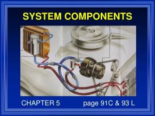
System Components
System Components. North Seattle Community College HVAC Program Instructor – Mark T. Weber, M.Ed. Lesson Objective. Component Review Compressor. Condenser. Metering device. Piping. Refrigerant. Introduction.

System Components
E N D
Presentation Transcript
System Components North Seattle Community College HVAC Program Instructor – Mark T. Weber, M.Ed.
Lesson Objective • Component Review • Compressor. • Condenser. • Metering device. • Piping. • Refrigerant.
Introduction • Air conditioning is the process of cleaning, tempering, and humidifying or dehumidifying indoor air and distributing it throughout the conditioned space quietly. • Filtration also is important. • Systems are designed with individual pieces. • Technicians must understand all components.
Compressors • Heart of the system. • Serves as a pump: • Circulates refrigerant; and • Compresses low-pressure vapor to high-pressure vapor. • Operation of other system components is dependent on the compressor.
Pumping Ratio • Also called “compression ratio.” • Absolute discharge pressure divided by absolute suction pressure: Ex: 240 psig discharge pressure, 75 psig suction pressure; • Discharge Psia = 240 +15 = 255; • Suction Psia = 75 + 15 = 90; • Compression ratio = 255 ÷ 90 = 2.83; • Compression ratio = 2.83:1; and • No higher than 4:1.
Hermetic Compressor • Internal parts not serviceable. • Cooled by suction vapor. • Heat-pump compressors run hotter than A/C applications. A hermetic compressor (The most common) utilizes suction vapor to cool the motor. Heat-pump compressor motors run hotter than cooling-only unit compressors because of the low refrigerant density at low suction pressures. Some designs take this into account and route the suction vapor through the motor windings.
Mineral Oils/Lubrication • Lubricant is important. • Oil selection is application-specific. • Oil travels through the system with refrigerant and tends to migrate. • Crankcase heater boils off liquid refrigerant from oil in the compressor crankcase. Mineral oils used in cooling-only applications do not perform well in heat-pump applications. These oils are simply too viscous (thick) in cold weather to provide good lubrication of internal compressor parts. A specially designed lubricant must be used in compressors for systems that will be operated in very cold weather. It is low-foaming white oil. Compressors lubricated with standard mineral oil typically are intended to be turned off when the outdoor air temperature drops to approximately 40°F–45°F. Lubrication is very important. During the heating cycle, or when the system is switching from the heating cycle to the defrost cycle and back again, liquid refrigerant can enter the compressor due to the lower operating temperatures. The vapor pressure of the oil is lower than the vapor pressure of the refrigerant. If refrigerant is allowed to migrate to the compressor during “OFF” cycles, it will condense in the oil sump. Liquid refrigerant must be kept out of the lubricant in the compressor. Crankcase heat is used to raise the vapor pressure of the oil to a point above that of the refrigerant, thus preventing liquid from condensing in the sump oil. Crankcase heaters are often de-energized when the compressor is running, and energized when the compressor is off.
Compressor Types • Reciprocating. • Scroll. • Rotary. • Screw. • Centrifugal. Types of compressors used in modern HVACR applications include reciprocating, scroll, and rotary compressors. Most manufacturers use reciprocating (piston-drive) and scroll compressors today. Reciprocating compressors usually are found in smaller-capacity systems (2-ton units and smaller), while scroll compressors typically are used in systems with larger capacities.
Compressors: Vapor Pumps • Not designed to pump liquid. • No compressor type can accomplish this: • Scroll compressors can let a small amount of liquid pass though. • Compressor must have refrigerant vapor ONLY at the suction inlet. Compressors are vapor pumps. No compressor is designed to pump liquid refrigerant, which is not compressible. Attempting to pump it through a vapor pump is dangerous because the pressures generated can damage valves, the piston and components used to connect the piston to the crankshaft. Scroll compressors can pass small amounts of liquid refrigerant—however, the process is noisy and would likely be of concern to most consumers. In addition, the liquid refrigerant works like a detergent and scrubs oil from the scroll members, thus diminishing lubrication. In all cases, it is important to ensure that only dry suction vapor enters compressors used in vapor-compression systems!
Compressor Motor Cooling • High temperature and fully hermetic compressors are typically refrigerant cooled. • Flow of the cool refrigerant vapor is directed across the motor before it enters the head of the compressor to cool the motor. • High superheat or reduced suction pressure will reduce motor cooling capacity.
Condenser • The condenser must reject heat from multiple sources: Heat absorbed in the evaporator; • Heat added in the suction line; • Heat added in the liquid suction heat exchanger; • Heat of compression; and • Heat from the compressor motor on refrigerant-cooled compressors. The condenser is a heat-exchange surface that permits the transfer of heat from the refrigerant to a condensing medium. The condenser must reject heat from the load being cooled, the superheat added in the evaporator and the heat generated during compression. The condensing medium can be air, water, or a combination of air and water. It must be at a temperature lower than that of the refrigerant being condensed (because heat always travels from warmer substances to cooler substances).
Condenser • The refrigerant will enter the condenser as a highly superheated vapor: • Temperature must be dropped to saturation point. • The refrigerant is condensed: • Latent heat is removed. • The refrigerant must be subcooled: • This ensures that all refrigerant has condensed and refrigerant won’t flash off in the liquid line due to pressure drop.
Condenser • Refrigerant leaving the compressor is superheated and is well above the saturation temperature. Therefore, it must be cooled down to the saturation temperature before it can be condensed. This process is called de-superheating. As the vapor temperature decreases during this process, the work done on the refrigerant is sensible heat. In residential systems, approximately 5% of an air-cooled condenser coil is used to remove superheat from the vapor. • When the vapor has been de-superheated, it can be condensed. The condenser continues to remove heat energy from the refrigerant—however, during this phase of the process, the refrigerant changes state from vapor to liquid while the temperature and pressure remain unchanged. Since the temperature is constant during this process and a change of state occurs, the work done on the refrigerant is latent heat. In residential systems, approximately 85% of the condenser coil is used to remove the latent heat from the refrigerant. • The warm liquid refrigerant is now at the saturation point, and at a temperature several degrees above the outdoor air temperature. It is not desirable for saturated liquid refrigerant to leave the condenser, because even a slight pressure drop in the liquid line can cause the liquid to flash, and bubbles to appear. A solid column of liquid must reach the metering device or capacity losses will result. • To prevent this from happening, the condenser now mustsubcoolthe liquid refrigerant before it enters the liquid line. Since the liquid temperature decreases during this process, the work done on the refrigerant is sensible heat. In residential systems, approximately 10% of the condenser coil is used to subcool the liquid.
Condensers • Larger coil surface increases the rate of heat transfer. • Proper matching to indoor coil is critical. From this discussion, you can see that both sensible heat energy and latent heat energy are removed from the refrigerant by the condenser. However, most of the work done on the refrigerant is transferred as latent heat energy. A larger condenser coil provides a more effective surface area, which increases the rate of heat transfer. This yields lower head pressures and more subcooling, thereby reducing the temperature of the warm liquid. By lowering the liquid temperature, the net refrigeration effect is increased in the evaporator. Flash gas bubbles that appear in the metering device are sacrificed to cool the remaining warm liquid down to the desired evaporator temperature. Lower-temperature liquid leaving the condenser translates to less cooling of the liquid needed at the metering device, which allows more of the flash gas to cool the load. Manufacturers also add more fins per inch of coil tubing to increase heat transfer and system efficiency. Outdoor coils used in air-to-air heat-pump applications have more surface area and internal tubing volume than do the indoor coils used in the matched system. The internal coil volume of the outdoor coil may be 1.2 to 2.0 times greater than the indoor coil volume. This relationship is important because the refrigerant condenses in the indoor coil during the heating cycle. As the liquid volume within a condenser increases, the head pressure also increases because the internal volume available for hot vapor decreases. Therefore, it is very important that the indoor and outdoor sections be correctly matched by following manufacturer guidelines.
Condensers • Only manufacturer-approved matches should be installed. • Heat-pump coils typically have more circuits than cooling-only systems. For example, consider a system that has an outdoor coil with twice the internal volume of the indoor coil. Condensed liquid that takes up 10% of the larger outdoor coil could take up 20% of the indoor coil volume during the heating cycle. If the outdoor unit with that coil is mismatched with an older existing indoor unit—one with a coil that is too small—problems will result. If the volume of the coil in the new outdoor unit is 2.5 times greater than the volume of the older existing coil, liquid could take up 25% of the indoor coil volume during the heating cycle, causing high head pressures. This explains why technicians must add refrigerant to mismatched heat-pump systems in the summer and remove refrigerant in the winter to keep them operating. Only manufacturer-approved matched systems should be installed. Coils used in the outdoor section of a heat-pump system typically have more circuits than outdoor coils used in cooling-only systems. Because the outdoor section of a heat pump functions as an evaporator during the heating cycle, pressure drop through the coil must be minimized to provide an adequate refrigerant flow rate. Adding circuits reduces pressure drop through the outdoor coil.
Condensers • Condensing temperature of lower-efficiency condensers is approximately 30°F higher than the outdoor air temperature. • Higher-efficiency systems may have condensing temperatures that are less than 15°F higher than the outdoor air.
Water-cooled Condenser • Closed loop: • Water circulates through a loop of pipe buried in the ground, run through a building, or a secondary heat exchanger (dry cooler). • Open loop: • Water pumped from a source and dumped; and • Cooling tower (commercial). An air-cooled condenser loses capacity and efficiency during periods when the outdoor ambient temperature is high. Many system designers prefer to use water-cooled condensers to improve system performance during hot weather. Water-cooled condensers do not use fans to circulate air that serves as a heat sink for the heat rejected from the refrigerant. Rather, they use water as the condensing medium. Therefore, they are less sensitive to changes in outdoor air temperature. Water-cooled condensers are less likely to experience large fluctuations in high-side pressure and condenser saturation temperature. This is due to the fact that the water is at a more or less constant temperature. Two popular types of water systems used for condensers of this type are closed-loop and open-loop systems. Closed-loop systems are used to recirculate the water through a sealed piping system buried in the earth or submerged in a pond. Open-loop systems are used to draw ground water, pump it through the condenser, and return it to the earth. The water must be returned to the same aquifer from which it was drawn. The well must be constructed so that the borehole does not interconnect different aquifers or zones. The simplest way to comply with this requirement is to grout the entire borehole from bottom to top. Either bentonite grout or “thermally enhanced” bentonite-sand mixtures may be used. In some areas, open-loop systems are not allowed due to concern for potential contamination of ground water. You should always confirm state, county, and municipality requirements for construction and operation of well systems used for HVACR applications.
Metering Devices • Also called an “expansion device.” • Create a pressure drop. • Feed liquid refrigerant into the evaporator. The refrigeration cycle is a closed-circuit operation that continually repeats itself. Refrigerant does not “wear out” with use, so long as the system is maintained properly and contaminants are kept out of the circuit. As was explained earlier, desired temperatures at various points in the system are established by mechanically manipulating internal pressures exerted on the refrigerant. Varying the pressures changes the boiling point of the refrigerant, which gives system designers the ability to determine a close range of temperatures for the evaporating and condensing of the refrigerant. You already know that the compressor adds heat to the vapor to raise its temperature before it is pumped into the condenser. The component that lowers the pressure and temperature of the refrigerant in the system is the metering device (or expansion device). This device is responsible for feeding the correct amount of refrigerant into the evaporator. Liquid refrigerant arriving at the metering device is warmer than the outside air. Flash gas bubbles form as the liquid undergoes a pressure drop in the expansion device. Evaporating liquid absorbs heat when the bubbles are formed. The first substance cooled by this process is the remaining liquid refrigerant. Approximately 20%–25% of the liquid refrigerant is sacrificed to cool the remaining warm liquid down to the desired evaporator temperature.
Metering Devices: Fixed • Fixed orifice and capillary tube: • The capillary tube is a simple and inexpensive device. • The flow rate is determined by its length and inside diameter. • Used on smaller refrigeration systems.
Metering Devices: TXV • Thermostatic Expansion Valve: • TXV or TEV. • Three pressures: • Bulb; • Evaporator; and • Spring. • A thermostatic expansion valve (abbreviated TEV, or TXV) is a modulating device that opens and closes in response to suction-line superheat. This action regulates refrigerant flow into the evaporator. The TEV is designed to maintain a constant evaporator superheat. • A thermostatic expansion valve (shown in the image on this slide) must meter the flow of liquid refrigerant entering the evaporator at a rate that matches the amount of refrigerant being boiled off in the evaporator. This is the main purpose of a TXV—however, like all other metering devices it also causes a pressure drop in the system. This separates the high-pressure side of the system from the low-pressure side and allows low-pressure refrigerant to absorb heat. The valve has three forces acting upon it to accomplish this task. They are: • bulb pressure (P1); • evaporator pressure (P2); and • spring pressure (P3).
Externally Equalized TXV • Allows measurement of the evaporator pressure at the outlet of the evaporator. • Prevents “hunting”—alternate overfeeding and starving of the evaporator. • An externally equalized TXV has a fitting on the side of the valve body for a tubing connection. The tubing connects the valve’s equalizer circuit to the suction line at a point leaving the evaporator. This allows the valve to sense suction pressure at the TXV bulb location properly. An externally equalized TXV must be used when the pressure drop (converted to change in corresponding saturation temperature) across the evaporator exceeds the following values: • 3°F for air conditioning; • 2°F for refrigeration (and heat pumps operating in the heating cycle); and • 1°F for low-temperature applications. • Single-ported valves are susceptible to hunting, which is caused by the alternate overfeeding and starving of refrigerant flow to the evaporator. Hunting may be observed on the suction gauge when the suction pressure rises and falls constantly as the compressor operates. Hunting can be reduced either by relocating the sensing bulb to a better location or by installing a valve designed for reduced hunting.
Sensing-bulb Location • The sensing bulb must be securely mounted to the suction line. • The sensing bulb must be properly insulated. • The sensing bulb my be located on the top of ⅞-in. or smaller lines. • The sensing bulb should be mounted at the 4 o’clock or 8 o’clock position on larger lines.
TXVs Require Liquid Input Faults that could create unacceptable pressure drops across the liquid line (and thus liquid-vapor mixture to TXV) include: • Restricted liquid-line filter-drier; • Excessively long liquid line; • Liquid-line tubing diameter that is too small; • Kinked liquid-line tubing; and • Insufficient refrigerant charge.
Evaporators • The evaporator will boil the refrigerant and absorb heat from the air or water. • An air-conditioning evaporator must operate at a temperature below the dew point of the air. • A larger size coil will contain multiple parallel circuits to reduce pressure drop. • A distributor ensures even flow of the refrigerant into all circuits.
Evaporators • The evaporator is the system component that contacts the air being recirculated by the blower in an air-handling unit or a furnace. It is the cooling coil that actually performs the work on the air by lowering its temperature and moisture content (humidity). Therefore, the temperature of the tubing and fins of the evaporator must be maintained at a temperature below the dew point temperature of the indoor air. Evaporators also can be used to remove heat from water to provide heating for a home or office in the winter. • Refrigerant in the evaporator is able to maintain a low temperature because its pressure is greatly reduced by the combined effects of the compressor suction valve and the metering device. As long as the refrigerant is saturated, its temperature at a given pressure is determined by a known pressure-temperature relationship. As the refrigerant flows through the evaporator, heat is transferred from the air or water passing over the coil to the refrigerant flowing inside the coil. As heat is absorbed by the refrigerant, more of the liquid boils into a vapor. The work done on the refrigerant at this point is latent heat, because the refrigerant is changing state at a constant temperature. When all of the liquid boils off, the suction vapor will continue to absorb heat from the load as it superheats. The work done on the refrigerant at this point is sensible heat, because the refrigerant increases in temperature. • Evaporator tubing is enhanced with spiral scoring on the interior tube walls. This scoring agitates the expanding liquid to keep the inside of the tubing wet with evaporating liquid refrigerant for maximum cooling effect. Before the refrigerant leaves the evaporator, all liquid must be evaporated and superheated to ensure that only dry vapor reaches the compressor. Cooling coils used in comfort systems are dry-type evaporators known as direct-expansion (DX) evaporators. They are designed so that under normal operating conditions all of the refrigerant will boil off into vapor before leaving the coil. • As evaporators increase in size, the amount of tubing and bends used to fabricate the coil also increases. This causes the pressure drop through the evaporator to increase. The pressure at the outlet of an evaporator may be several pounds less than the pressure at the inlet of the coil. This condition is undesirable but can be averted by the use of a multi-circuit evaporator. As the name implies, these evaporators are made up of two or more parallel circuits rather than one large circuit. A multi-circuit evaporator uses a refrigerant distributor to ensure that the refrigerant is distributed evenly between all of the individual evaporator circuits.
Evaporators • Types: • A-coil; and • Horizontal slab. • In heat pumps the outdoor coil becomes the evaporator during the heating mode.
Accumulators • Accumulators are added to the suction line to collect and boil off any liquid refrigerant in the suction line before it can reach the compressor. • Receivers store refrigerant: • Optional component. • Located between the condenser and the metering device.
Refrigerants Saturation point at atmospheric pressure • R-22: • Mineral oil. • R-410A: • Polyolester (POE) oil. • No ozone depletion • (Not really).
Refrigerants • Decomposition occurs if refrigerant is exposed to high temperatures: • Never solder or braze without purging the piping with nitrogen and ventilating the area. • Inhaling concentrated vapors can cause heart irregularities and unconsciousness.
Refrigerant Cylinders • DOT has jurisdiction over shipping and labeling of cylinders. • Maximum storage temperature is 125°F. • Never fill more than 80%.
Tubing • Approved for ACR applications. • Inspect and leak-test all soldered and brazed joints. • Leak test with dry nitrogen: • Never use compressed air; and • Never use oxygen. • Purge lines with nitrogen when brazing. • Use neutral flame with oxyacetylene torch.
Piping • Keep lines as short as possible. • Use long-radius elbows. • Keep fittings to a minimum. • Pitch vapor lines toward the compressor. • Insulate vapor lines: • Liquid lines in high temperatures. One of the most important functions performed by a system installer is the installation of the refrigerant lines. Poorly installed tubing can result in premature failure of the compressor, as well as a system that does not operate effectively and efficiently.
Piping • Inspect and leak-test all brazed and soldered joints. • Install traps on vertical risers when necessary. • Keep tubing capped to keep it clean. • Evacuate system to at least 500 microns.
Piping • Use of soft-drawn copper can reduce the number of fittings. • Bend soft-drawn tubing with spring or lever bender. • Never cut with a hacksaw. • Pressure drop in a suction line should not exceed 2°F.
Piping • Bending tools can only be used on soft-drawn copper. • Length and diameter are important. • Excessive pressure drop across a liquid line must be avoided. These causes include: • Excessiveliquid-line length; • Excessive liquid-line lift; • Tubing diameter that is too small; • Kinks in the liquid line; and • Too many elbows and/or the use of short-radius elbows.
Summary • By adding a reversing valve and check valves to a system, the basic refrigeration cycle can be manipulated to provide heating in winter as well as cooling in summer. • In order to service comfort cooling and heat pump systems successfully, a technician must understand the principles at work in a closed vapor compression cycle. • The term “closed” indicates that the cycle continually repeats itself without depleting the refrigerant contained within it.