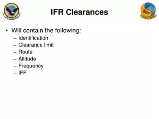
IFR COM-120B Training Program
IFR COM-120B Training Program. Course Outline. Basic Instrument Front Panel Connections Rear Panel Connections Navigation RF Generator Screen Zooming Meter Functions Receiver Screen Duplex Operation Scope Spectrum Analyzer Tracking Generator Applications. Stored Setups


IFR COM-120B Training Program
E N D
Presentation Transcript
Course Outline • Basic Instrument • Front Panel Connections • Rear Panel Connections • Navigation • RF Generator Screen • Zooming • Meter Functions • Receiver Screen • Duplex Operation • Scope • Spectrum Analyzer • Tracking Generator Applications • Stored Setups • StoredFrequency List • Memory System • StoringandRetrieving Images • PCMCIA Card Slot • Printing and Capturing • EDACS • BER • Applications Library • EasySpan for Windows • EasySweep
COM-120B Basic Instrument • 250 kHz to 1 GHz Full Featured Service Monitor • RF Signal Generator • Sensitive 2 uV Receiver • Cross Band Duplex • High Speed Digitized Spectrum Analyzer • High Speed Digitized Scope • Generate and Demod FM, AM, PM • AC, Battery and Ext. DC operation • 38.5 lbs.
COM-120B Standard Features • RF Signal Generator • Output Level +13 to -130 • 0.2 PPM TCXO • 2 uV Receiver with 15, 30 and 300 kHz IF filters • 50 kHz Scope • Full band / Dual Mode Spectrum Analyzer • Digital Voltmeter • Audio Level Meter • Dual Audio Function Generators • Data Generator DCS, DCS INV • DTMF Generator • Encode / Decode • DCS, DTMF, CTCSS • RF Frequency Error Meter and Counter • FM Deviation Meter • AM Modulation Meter • Phase Modulation Meter • Audio Frequency Counter • RF Power Meter (2 mW - 200 W) • 50 W Continuous • RF Level Meter • Distortion Meter • SINAD Meter • RS-232
Options and Accessories • EDACS Trunking (AC3016) • 7.5 kHz IF Filter (AC9162) • SSB Filter (120B-8xx) • Microphone (AC8645) • Antenna (AC1201) • Heavy Duty Ship case (AC8753) • Soft Padded carry case (AC9925) • IEEE-488 Interface (AC3013) • EasyCom Land Mobile test software (AC1022) • Application Library (AC1023) • Nortel Cellular Base Station Software (AC1037) • Programming Manual (AC0301) • Maintenance Manual (AC0600) • Extended Warranty 3/5 year • 0.01 PPM OCXO (120B-xTx) • Internal Rechargeable Battery (AC3001) • Tracking Generator (AC3012) • Return Loss Bridge (AC4105) • EasySweep Software (AC1019) • EasySpan for Windows (AC1009W) • Digital / Analog Signaling (AC3011) • CCIR, CCIRH, CCIRH4, EEA, • EIA, NATEL, ZVEI, DZVEI, • DDZVEI, EURO, 5/6 Tone, POCSAG • RCC Signaling (AC3009) • Tone Remote, IMTS, MTS, 10 PS, 20 PS • Data Generator / BER Meter (AC3007) • MPT-1327 Trunking (AC9161) • Clear Channel LTR Trunking (AC3014)
RF Input and Outputs Off the Air Monitoring Transmitter connection Full Duplex Testing Half Duplex Testing and Tracking Generator Output Receiver Transmitter
Audio Input and Outputs Scope / DVM Input AUDIO / DATA SINAD IN Ext Mod source for radio under test AUDIO / DATA GEN OUT EXT MOD IN DEMOD OUT Ext Audio Analysis
Rear Panel Master Power Switch Battery Compartment Ext. DC Input RS-232 Serial IO Direct pin to pin connection to PC Optional GPIB Interface 10 MHz Ext Ref Input
Navigation The Arrow keys are used to position a cursor to an EDIT FIELD. The TAB Key allows direct access to any field on the screen and is an alternative to incrementing the cursor through other fields. Function Keys pertain to the Field Selection.
RF Generator (Receiver Testing) AUX Gate SET REF T/R Gate SWEEP C-Fwd V D= T/R On/Off dBm T-Rvs mV C-Rvs SINAD= LOCK uV D on/off T-Fwd AUX S=On/Off FL RF Generator (Receiver Testing) RF FL Level Output
Stored Frequency List Up to 100 frequency pairs may be stored Labels allow for easy selection of the correct frequency pair. Program the Frequency List by pressing the SHOW LIST key on the front panel SHOW LIST Access the stored frequency list by enabling FL on the Frequency field of the Generate or Receive screens
Modulation Sources Modulation Sources This area identifies what sources are turned on GEN1 indicates that FGEN 1 is turned on GEN1B indicates that FGEN1 is turned on but is in BURST mode The Gen 2 Source field can be configured for a CTCSS Tone OR The DATA generator could be used to configure a DCS code for digital squelch systems. The Gen 1 Source field can be configured for a standard 1 kHz tone
SINAD Meter Filtering The SINAD meter is commonly configured with a C-MSG filter. Setting the SPEAKER/PHONES to C-MSG allows the AUDIO/DATA SINAD Input port to be routed to the speaker.
Zooming Zooming Placing the cursor on the SCOPE / ANALYZER or METER field allows access to additional controls for that device.
Meter Functions Meter Functions Scope or Analyzer can be displayed Additional Controls Bar Graph Meter
Generate - AF Level Meter • Adjust volume or audio to specific levels prior to Distortion or SINAD measurements. • Measure Vrms • Measure dBm (user enters desired load value) • Measure dB relative
Testing Receiver Audio BW The Audio BW of the receiver can be measured by setting a reference at 1 kHz then adjust the tone frequency from 300 Hz to 3 kHz while the Audio Level meter is in dB mode.
Generate - SINAD Meter Positioning the cursor to the RF Level field allows automatic search for specified SINAD reading. Setting the SINAD meter to Average mode with 10 averages will make the readings more stable when manually searching for 12 dB SINAD readings. Scope source can be set to view Internal Modulation source, Audio/Data Input port or Notch Residual to evaluate receiver performance. Note: Averaging should be turned off when performing automatic SINAD search operations.
RF Signal Generator Receiver Under Test Audio Output Audio Filter R.M.S. Voltmeter Notch Filter R.M.S. Voltmeter Testing Receiver Sensitivity SINAD = Signal + Noise + Distortion Noise + Distortion
Testing Receiver Distortion After setting the Audio output level to 60% of the rated audio level, the receiver distortion can be measured. Reducing the audio level by 20dB should result in a distortion indication of less than 10%.
Generate - Spectrum Analyzer Modulation Index for a 1 kHz Rate Rate= Desired Dev (Hz) / Mod Index 3300 Hz Dev / 2.405 = 1372.1 Hz for Carrier Null (52 dB)
Receiver (Transmitter Testing) CF IF BW SWEEP C-Fwd 300 kHz On/Off FM 30 T/R D= PM 30 kHz SCAN T-Rvs C-Rvs LOCK 15 kHz T-Fwd 0 ANT D on/off AM FL Receiver (Transmitter Testing) RF FL INPUT Atten Demod IF BW 26 dB BW required to demodulate signal
AFGEN Out The internal function generators can be used to externally modulate the transmitter. Two variable rate function generators, DTMF, DCS, Ext Mod source and Microphone sources are available.
Post Detection Filters Post Detection Filters Careful attention to filter settings must be maintained to avoid measurement errors.
Tone Decoding Care must be taken to ensure that the Filter for the Audio Counter is set correctly prior to decoding.
RF Frequency Error Meter Frequency tuning can be easily done by setting the Range to a fixed range. Set the Gate time to 0.1 S to take fast readings
Audio Frequency Counter The Audio counter offers more resolution when zoomed. For rates less than 300 Hz, 0.1 Hz resolution can be obtained with a 1 S gate time.
RF Power Meter The dBm scale provides a convenient way to measure cable loss by using a reference cable. A 0.4 dB cable loss can cause 10% error in Power measurement. If not accounted for.
RF Level Meter Measures the signal strength an off the air signal through the Antenna port. The level may vary with different IF bandwidth selections. For maximum accuracy, perform the SET LVL calibration procedure.
Deviation Meter The Deviation meter must be zeroed when DC coupled. When AC coupled, zeroing is not required. Transmitter Maximum deviation is the greater of the two values 1.11 - 1.10 Deviation Symmetry = Deviation (higher) - Deviation (lower) X 100 = 0.9% Deviation (higher) 1.11
Duplex Operation Move the cursor to these fields to expand the screen to access all of the Receiver or Generator functions. • Simultaneously Generate and Receive operation for Full Duplex • Any Offset between Generate and Receive frequencies in 2.5 kHz steps
Oscilloscope Trigger Modes: NORMAL AUTOMATIC 1 SHOT Display Modes: LIVE AVG RECALL MIN HOLD COMPARE PK HOLD LIVE-REF STORE REF-LIVE
Scope Input Selections INTERNAL INPUTS: Detector Out Data Decoder Audio/Data Gen Out RF Power Notch Residual Demod Out Conn. AF Cntr Mod Meters DTMF/SINAD EXTERNAL INPUTS: SCOPE/DVM - GND SCOPE/DVM - AC SCOPE/DVM - DC
Peak Hold Feature • The scope PK and MIN Hold feature allows monitoring of maximum and minimum modulation variations. • Monitor FM or AM Broadcast • Monitor Transmitter Deviation
Spectrum Analyzer • Independent control of Sweep Rate and RBW • Reference Level Offset adjustment • Offset Tracking Generator • Signal Find feature • Split Screen / Dual mode operation • Zero - Full Span display modes in 1,2,5 sequence
Spectrum Analyzer Marker REF Scale Units Track Gen ON/OFF DEFAULT LOCK CONFIG Center Freq Offset Span Sweep RBW COUPLE DFLT Frequency SET REF FIND FIND LVL CONFIG Sweep Width Split Mode AVG RECALL PK Hold COMPARE MIN Hold LIVE-REF STORE REF-LIVE LIVE
Peak and Min Hold • Like the scope, the Spectrum Analyzer supports a Peak and Min hold feature. • Verify signal amplitude does not vary • Verify that a channel does not go off the air. • Verify presence of spuratic interference signals. • Identify the frequency of pulsed or short duration signals.
Using the Tracking Generator for Antenna Isolation The problem: How to ensure that RX and TX antennas are sited correctly to maximize isolation and thereby prevent RX desensitization? Solution: Tracking generator swept across TX band with RX antenna connected to analyzer input. RX in TX out
The Return Loss Bridge (AC4105) Return Loss Bridge Signal Generator DUT Port Source Reflected Return Loss is the difference between a measured reference signal, and the measured DUT . It can be used to check the degree of mismatch of filters, antenna’s, receiver inputs, amplifier inputs and isolators. Spectrum Analyzer CAUTION: Measurements cannot be made beyond the directivity (resolution) of the bridge itself.
Antenna Measurements using a Return Loss Bridge (AC4105) Antenna VSWR / Return Loss Measurement Reflected VSWRBridge Source Out (DUT)
492 * Vel. Factor Distance ft.= Delta Freq. in MHz Using the Tracking Generator for Cable Fault • This image shows a series of nulls due to an open at the end of a cable • Specialized software allows calculation of distance EasySpan for Windows Antenna Input Tee connector on Tracking Generator (AUX) Output Cable under test
Using the Tracking Generator for Filter Tuning • This image indicates the characteristics of a filter • Notch depth of 86.78 dB • Frequency tuned to 461.8358 MHz • 3 dB Bandwidth of 198.4 kHz • Measurements • Notch Depth • Bandwidth • Insertion Loss at Passband
Duplexer Tuning • Split screen mode makes Duplexer tuning easy. • Set a 0 dBm reference with cables. • Switch between 0 and 30 dB input attenuation to tune for insertion loss or notch depth. Simultaneously view wide and narrow windows Additional range can be obtained by reducing the Resolution Bandwidth and slowing the sweep speed.
Store and Recall Up to 50 Storage Locations are available. Storage Locations are labeled 0 - 49. Screen settings that are saved are: Generator, Receiver, Duplex Generator
2.5 MB Internal File System Formatting of the File System is similar to a standard DOS file System. Access the File system through the SHOW LIST key.