Understanding Wave Interference: Principles and Experiments
This chapter delves into wave interference and the principle of superposition, which states that the displacement of waves at any point is the sum of the displacements of all interacting waves. It explains constructive and destructive interference, characterized by the interaction of coherent waves. Through experiments, such as observing water waves using a ripple tank, we explore how wavelength affects the distance between nodes and antinodes. The analysis ultimately reveals that increased wavelength leads to greater distances in the interference pattern.

Understanding Wave Interference: Principles and Experiments
E N D
Presentation Transcript
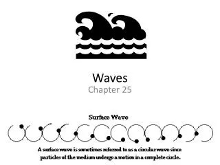
1. Chapter 1: Waves 1.5 Analysing Interference of Waves
2. Principle of Superposition 1 The Principle of superposition states that at any instant, the wave displacement of the combined motion of any number of interacting waves at a point is the sum of the displacements of all the component waves at that point.
3. Principle of Superposition 2 Figures 1.46 (a), (b) and (c) show the combined amplitude produced when two waves, both of amplitude a, from opposite directions meet.
4. Principle of Superposition
5. Principle of Superposition 3 Interference pattern is a result of the superpositions of waves.
6. Interference of Waves 1 Interference is the superposition of two waves originating from two coherent sources. Sources which are coherent produce waves of the same frequency (f), amplitude (a) and in phase.
7. Interference of Waves 2 The superposition of two waves emitted from coherent sources gives either constructive or destructive interference.
8. Interference of Waves 3 Constructive interference occurs when the crests or troughs of both waves coincide to produce a wave with crests and troughs of maximum amplitude.
9. Interference of Waves 4 Destructive interference occurs when the crest of one wave coincides with the trough of the other wave, thus canceling each other with the result that the resultant amplitude is zero
10. Interference of Waves 5 Figure 1.47 shows the occurrence of constructive interference and destructive interference.
11. Interference of Waves 6 An antinode is a point where constructive interference occurs, whereas a node is a point where destructive interference occurs. From Figure 1.48, it can be seen that the antinodes line joins all antinodes while the node lie joins all nodes.
12. Interference of Waves Keys:
� -maximum crest waves (two crests meet)
x -zero amplitude waves (trough meets crest)
o -maximum trough waves (two troughs meet)
13. Interference of Waves Experiment 1.8 : To investigate the interference of water waves
(I) Different wavelengths ( )
Problem statement
What is the relationship between the wavelength, ?, and the distance between two adjacent node lines (or antinode lines), x, in the interference pattern?
14. Interference of Waves Experiment 1.8 : To investigate the interference of water waves
(I) Different wavelengths ( )
Hypothesis
The distance between two adjacent node lines (or antinode lines), x, increases as the wavelength increases.
15. Interference of Waves Experiment 1.8 : To investigate the interference of water waves
(I) Different wavelengths ( )
Variables:
(a) Manipulated:Frequency of the dippers or wavelength
(b) Responding: Distance between two consecutive node lines, or, antinode lines (x)
16. Interference of Waves (I) Different wavelengths ( )
Variables:
(c) Fixed:
(i) Distance between two sources (a)
(ii) Distance from sources to the point where the distance between two adjacent node lines or antinode lines (x) is measured (D)
17. Interference of Waves (I) Different wavelengths ( )
Apparatus/Materials
Ripple tank, spherical dippers and mechanical stroboscope.
18. (I) Different wavelengths ( )
Procedure
1 A ripple tank is set up with two spherical dippers in contact with the surface of the water.
2 The distance between the two spherical dippers is fixed at 4 cm.
19. (I) Different wavelengths ( )
Procedure
3 The motor and the rheostat are adjusted to operate the motor at low frequency.
4 The pattern of the interference of the waves is observed with a stroboscope and the pattern is drawn.
5 Steps 3 and 4 are repeated with the vibrator operating at a higher frequency. The waves produced have a shorter wavelength.
20. Interference of Waves (I) Different wavelengths ( )
Observation
21. Interference of Waves (I) Different wavelengths ( )
Discussion
1 Table 1.2 shows that when the two waves combined to produce waves of larger amplitude as shown by the regions which are bright (where the crests of the two waves coincide) and the darker regions (where the troughs coincide). This part of the pattern of waves shows the crests and troughs which are reinforced as a result of constructive interference.
22. Interference of Waves Discussion
2 In some regions where the water is still, without any ripples, the crests and troughs of the two waves coincide and eliminate each other (destructive interference). Since the amplitude is zero, there is no wave motion.
23. Interference of Waves (I) Different wavelengths ( )
3 The results in Table 1.7 shows that when the frequency is higher, i.e., the wavelength is shorter, the distance between two adjacent node lines or antinode lines, x, is smaller.
24. Interference of Waves Conclusion
The distance between two consecutive node lines or node lines (x) increases when the wavelength of the water waves ( ) from the source increases.
25. Interference of Waves (I) Different wavelengths ( )
Conclusion
26. Interference of Waves (II) Different distances between the two sources of waves (a)
How is the distance between the two sources of waves, a, related to the distance between two adjacent node lines or antinode lines, x, in the interference pattern?
27. Interference of Waves (II) Different distances between the two sources of waves (a)
Hypothesis
If the distance between two sources of waves, a, is decreased, the distance between two consecutive node lines or antinode lines, x, increases.
28. Interference of Waves (II) Different distances between the two sources of waves (a)
Variables
(a) Manipulated : Distance between the two sources (a)
(b) Responding: Distance between the two consecutive node, or antinode lines (x)
(c) Fixed:
(i) Frequency of dippers (f) or wavelength (?)
(ii) Distance from sources to the point where the distance between two adjacent node, or antinode lines (x) is measured (D)
29. Interference of Waves (II) Different distances between the two sources of waves (a)
Apparatus/Materials
Ripple tank, Spherical dippers, metre rule and mechanical stroboscope
30. Interference of Waves (II) Different distances between the two sources of waves (a)
Procedure
1 The ripple tank is set up as shown in Figure 1.49.
2 The distance between two spherical dippers, a, is fixed at 4 cm.
3 The motor is switched on and the rheostat is adjusted to obtain waves with medium wavelength.
31. Interference of Waves (II) Different distances between the two sources of waves (a)
Procedure
4 The interference pattern is observed with stroboscope and the pattern is drawn.
5 Steps 3 and 4 are repeated with the distance between the two spherical dippers reduced to 2 cm
32. Interference of Waves (II) Different distances between the two sources of waves (a)
Observations
33. Interference of Waves Conclusion
The distance between two consecutive node (or antinode) lines, x, is inversely proportional to the distance between the two sources.
The hypothesis is valid.
34. Relationship between , a, x and D
35. Relationship between , a, x and D From the interference pattern (Figure 1.52) and factors that influence the interference pattern in Experiment 1.8, we found that
36. Relationship between , a, x and D Example 10
In the interference of two coherent sources of waves, the separation between two spherical dippers is 3 cm and the distance between two consecutive node lines is 4 cm measured at a distance of 15 cm from the two coherent sources of waves. Calculate the wavelength of the water waves originating from the sources.
37. Relationship between , a, x and D Example 10
Solution
Substituting a = 3 cm, x = 4 cm, D = 15 cm into the formula
? =
? =
= 0.8 cm
38. Interference of Light Waves 1 Interference of light waves, like that of water waves and sound waves, also requires two coherent sources.
39. Interference of Light Waves 2 Waves emitted from two coherent sources have the same frequency (or wavelength) and in phase.
40. Interference of Light Waves 3 Light emitted by a single source consists of waves which extend over a wide range of wavelengths and are not in phase. Because of this, it is difficult to have two sources of light which are coherent.
41. Interference of Light Waves 4 In 1801, Thomas Young produced two coherent light sources in his experiment now referred to as Young's double-slit experiment.
42. Interference of Light Waves 5 Principle of Young's double-slit experiment:
(a) Yellow light emitted by a sodium-vapour lamp has a very narrow frequency band. For all practical purposes, it can be considered as monochromatic light which is light of only one frequency or wavelength.
43. Interference of Light Waves 5 Principle of Young's double-slit experiment:
Figure 1.53 Young's double-slit experiment
44. Interference of Light Waves 5 Principle of Young's double-slit experiment:
(b) Slits S1, and S2 give rise to two coherent light sources since the light passing through them are from the same monochromatic light, the sodium-vapour lamp.
45. Interference of Light Waves 5 Principle of Young's double-slit experiment:
(c) Interference occurs as a result of the superposition of the two light waves originating from S1 and S2. A pattern consisting of a series of parallel and alternating bright and dark fringes is formed.
46. Interference of Light Waves (d) The bright fringes are regions where constructive interference occurs, whereas the dark fringes are regions of destructive interference.
47. Interference of Light Waves 5 Principle of Young's double-slit experiment:
(e) Figure 1.54 shows the interference pattern obtained in Young's double-slit experiment.
Figure 1.54
48. Interference of Light Waves 5 Principle of Young's double-slit experiment:
(f) The widths of the bright and dark fringes are the same.