Download
1 / 21
220 likes | 480 Vues
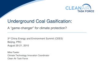
DEVELOPMENT OF A FLUIDIZED BED COAL GASIFICATION TECHNOLOGY Jerzy TOMECZEK Department of Process Energy Silesian University of Technology Presentation, Gliwice, 22 November 2005. RESEARCH ACTIVITY Clean Coal Technologies: · Gasification, · Combustion. Low Pollutants Emission Combustion:

E N D
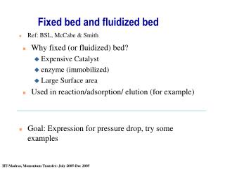
DEVELOPMENT OF A FLUIDIZED BED COAL GASIFICATION TECHNOLOGY Jerzy TOMECZEK Department of Process Energy Silesian University of Technology Presentation, Gliwice, 22 November 2005
RESEARCH ACTIVITY Clean Coal Technologies: ·Gasification, ·Combustion. Low Pollutants Emission Combustion: ·Mechanisms of NOx Formation, ·NOx Abatement Technologies. Heat and Mass Transfer in Furnaces: ·Mathematical Modelling, ·Semi-Isothermal Combustion Conditions, ·Fluidized Bed Structure Modelling, ·Prediction of Deposits in Boilers.
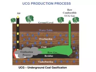
CONCEPT OF ELEKTRO-GAS PLANT COAL FUEL GAS DEVOLATILIZER LIQUID HYDROCARBONS CHAR GASIFICATION ELECTRIC ENERGY
RANGE OF PARAMETERS USED IN GASIFICATION EXPERIMENTS
D3 D3 D3 D2 D2 D2 1.5 m 2.0 m 1.5 m 1.3D1 1.3D1 D1 D D D Characteristic of tested variants of reactor geometry: D=100mm, D1=140 mm, D2=240 mm, D3=300 mm.
LOWER GAS HEATING VALUE, MJ/m3 COAL/AIR RATIO kg/kg Gas heating value as function of coal/air ratio for : 1- coal ● – A and ▲ - B, d=1.0-1.5 mm; 2- coal○ – A and Δ - B, d=0.5-1.0mm; 3 - char ■ – C and □ - E.
LOWER GAS HEATING VALUE,MJ/m3 STEAM/AIR RATIOkg/kg Gas heating value as function of steam/air ratio: 1- char Δ – C, □ - D and ■ – E, Tb=900oC; 2- coal● – A and ▲ - B, d=1.0-1.5 mm, Tb=900oC.
DECOMPOSED STEAM XH2O, % STEAM/AIR RATIOkg/kg Decomposed steam as function of steam/air ratio: 1- coal ○ – A and ● – B, char ■ – C and Δ – D for Tb=900oC; 2- coal for Tb=800oC by Tomeczek et al. (1983).
LOWER GAS HEATING VALUE, MJ/m3 PARTICLE RESIDENCE TIME t, min Gas heating value as function of bed residence time for air gasification and Tb=900oC: 1- coal ● – A and ▲ - B, d=1.0-1.5 mm; 2- coal○ – A and Δ - B, d=0.5-1.0mm; 3 - char ■ – C and □ - E, d=0.5-1.5mm.
CARBON CONVERSION xc, % PARTICLE RESIDENCE TIME t, min Carbon conversion as function of particle residence time for Tb=900oC: 1- coal ○– A and ● - B air gasification; 2- char Δ – C, ◊ - D and □ - E air gasification,▲– C and ■ -E steam - air gasification.
AMOUNT OF LIQUIDS, kg liquids/kg coal daf PYROLYSYS TEMPERATURE, oC Amount of liquids as a function of pyrolysis temperature: — coal “Siersza” (Tomeczek et al, 1988), —coal “Loy Yang” (Edwards et al, 1985) —coal “Millmerran” (Edwards et al, 1985), —coal eastern U.S. bituminous (Sass, 1988).
COAL GAS DEVOLATILIZER TAR CHAR HEAT AIR BOILER WATER COMBUSTION GASES STEAM Connection of a coal devolatizer with the boiler
CHARACTERISTICS OF THE 1, 15, 50 t/h DEMONSTRATION SCALE REACTORS CHARACTERISTICS OF 1, 15, 50 t/h REACTORS