Axle Counter: Enhancing Track Safety with Detection Technology
Learn about axle counters used in rail tracks to prevent accidents by detecting train presence and ensuring track safety. Understand how axle counting works, advantages of this technology, and its implementation in railways.


Axle Counter: Enhancing Track Safety with Detection Technology
E N D
Presentation Transcript
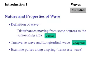
INTRODUCTION 1 What word comes to your mind to describe “The attempt by two objects to occupy the same space at the same moment in time”
INRODUCTION “ACCIDENT” This is something which signal engineers work towards ensuring do not happen while running trains. Therefore we need identification of this happening well in advance to ensure that trains can be stopped before this can occur.
TRACK CIRCUITS Track circuits are used to identify the presence of a train in particular section of a track and protect against accidents occurring on account of two trains moving to the same section of the railway track. Track circuits use various techniques and axle counting is one of them.
AXLE COUNTER • COUNTS AXLES • COUNTS AXLES IN AND OUT OF SECTION
HOW IT WORKS AS TRACK CIRCUIT • IF AXLES IN NOT EQUAL TO AXLES OUT THEN SECTION OCCUPIED SECTION IS OCCUPIED IN = 50 OUT = 0 SECTION IS OCCUPIED SECTION IS CLEAR IN = 50 OUT = 40 IN = 50 OUT = 50
ADVANTAGES • INSULATED TRACK NOT REQUIRED • INDEPENDENT OF BALLAST CONDITION • TRACK CIRCUIT LENGTH CAN BE UNLIMITED • VERY GOOD FOR PROVING BLOCK SECTION IS CLEAR • CAN OFFER COST EFFECTIVE SOLUTION IN MONITORING YARDS WITH SHARED PROCESSOR AND MULITIPLE DETECTORS
COUPLING OF SIGNAL FROM TRANSMITTER TO RECEIVER • Audio frequency signal from transmitter coupled electro magnetically to receiver coil is interrupted by passage of wheels causing dips which are counted Coupling above the rail Coupling below the rail
HOW DIPS ARE CREATED BY PASSAGE OF WHEEL • Wheel interrupts the signal coupled above the rail Coupling above the rail interrupted by wheel Coupling above the rail Coupling below the rail
VECTOR DIAGRAM OF SIGNAL With no wheel between the transmitter and receiver The Resultant signal is large and of phase about 0 deg With wheel between the transmitter and receiver The Resultant signal is smaller and phase also changes
SIGNAL CAN INCREASE WITH WHEELS Track devices do not necessarily have reduced coupling of magnetic field in the receiver coils when wheels traverse over it. In Siemens make axle counter track device the signal strength in the receiver coils increase when the wheels traverse over it. The main idea is that the signal changes as the wheel traverses over the track devices and its detection.
COUNTING OF AXLES • Earlier Axle counters only monitored the amplitude of the signal from detectors. • Present versions monitor both amplitude and phase. This gives additional discrimination between presence and absence of wheels.
DETECTION OF DIRECTION • Detection of direction of movement is important and it is done by having two detectors adjacent to each other. • Depending on the direction of movement the sequence of dips of the two detectors changes. Dip of A precedes that of B A A B B Signal Dip of B precedes that of A A A B B Time
COUNTING CIRCUITS • Dips are analyzed using failsafe electronic circuits and systems. • Older systems used discrete electronic circuits and then logic chips were used and presently processors are used • Multiple detectors are used to monitor point zones and even complete yard using shared processing equipment thus reducing cost and equipment.
DETECTION IN YARDS Detector 2 Detector 1 Detector 3 Detector 4 Processor based evaluating unit
DETECTION IN BLOCK SECTION Processor can include suitable logic to transfer information through radio or other telecommunication link Radio Link /OFC Processor Processor
TYPICAL AXLE COUNTER INDOOR EQUIPMENT Power supply CARDFILE Input Card Logic Card Output Card
TRACK DEVICE INSTALLATION TRACK DEVICE INSTALLATION The picture shows track devices fixed to the track. Receiver coil Transmitter coil
CLOSE LOOK AT TRACK DEVICE INSTALLATION Receiver coils Clamp Transmitter coils Base
TRACK SIDE JUNCTION BOX CEL The track side junction box provides matching of the signals to and from the track side to the Indoor processing unit. The junction box includes receiver amplifier, a transmitter and power supply. The transmitter is a audio frequency sine wave generator. There are separate outputs and inputs of the two transmitter and the receiver coils. The cable length from the junction box and the cable type is fixed to maximize signal strengths and improve noise immunity.
IMPLEMENTATION ISSUES 1 The output of the axle counter is fed to a relay. This relay is picked up when the section being monitored by the axle counter is clear of any trains as detected by the track device at the extremities of the section. RELAY EVALUATOR
IMPLEMENTATION ISSUES 2 This relay drops when the section being monitored by the axle counter is clear of any trains as detected by the track device at the extremities of the section. This relay contact is used in the signalling circuit similar to track repeating relay. TRAIN RELAY EVALUATOR
VALIDATION When a axle counter is started up it does not know the position of trains in the section it is monitoring. There is therefore the need to ensure that at start up it takes a safe state and that is it assumes that the section is occupied. The first train run and detected successfully is then used to allow the monitoring of the section by the axle counter. The signalling circuits are to be designed implementing this principle.
RESETTING Instead of running a validation train another method adopted is resetting of the axle counter by manual means to start the monitoring of the section. This can be safety risk and so normally procedure for resetting ensures more than one person will be be required to enable a reset. Resetting causes the counts recorded by the axle counter to be brought back to zero if there are any residual counts. So even if not used for validation is required to take care of counts registered due to unknown reasons.
MAINTENANACE Track devices require maintenance as the relative position of the transmitter coil, receiver coil and the rail on which it is fixed requires to be ensured for reliable detection of wheels of trains as it traverses the track devices. For proper adjustments dummy wheels are used which are moved across the track devices and the dip in the signal from the receiver coil ensured to meet the specifications.
PROBLEMS • Some of the main problems faced are • Unreliable wheel detection – caused by installation of the track devices or setting of signal levels. • Failure to detect fast trains – caused by improper adjustment of the track device coils. • Unreliable wheel detection during some periods of the day. Possibly due to defective track devices like fine cracks in the core material of the coils.