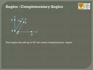
Diagnostic Angles
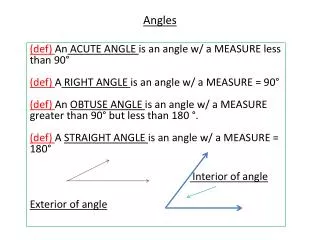
Diagnostic Angles. Diagnostic measurements. Diagnostic measurements are needed when basic alignment angles cannot be adjusted within specification or other problems not associated with basic alignment angles exist. Angle When to Use S.A.I./ IA Excessive front camber

Diagnostic Angles
E N D
Presentation Transcript
Diagnostic measurements • Diagnostic measurements are needed when basic alignment angles cannot be adjusted within specification or other problems not associated with basic alignment angles exist. Angle When to Use • S.A.I./ IA Excessive front camber • Set Back - Excessive front cross caster • Turning angle - Tire wear / squealing • Max steer angle - Tire wear • Symmetry Measurements Excessive dog tracking
Steering Axis Inclination • The Inward or Outward Tilt of the Steering Axis compared to a vertical line and viewed from the front • Steering Axis (red line) • Vertical line (blue line) • Benefits: • Directional stability • Returnability
SAI / IA Measurement • The front wheels are steered to measure SAI/IA.
Steering Axis Inclination • Bent front suspension components causing severe changes in front camber may be isolated using S.A.I. • Cross SAI equal or greater than 1.5 degrees • Bent upper control arm • Bent lower control arm • Collapsed strut tower • Damaged frame • Damaged or shifted sub-frame • Bent axle
Included Angle • Included Angle = SAI + Camber • Bent front suspension components causing severe changes in front camber may be isolated using Included Angle. • Cross IA equal to or greater than 1.5 degrees • Bent knuckle • Bent strut • Bent ball joint stud
Set Back • An angle formed between the centerline and a line perpendicular to the axle • Overlapping lines = Zero Set Back
Positive & Negative Set Back • Negative Set Back • Set Back left • Positive Set Back - Set Back right
Measuring Set Back • Select "Make Additional Measurements" • Select “Symmetry Measurements / Set Back” • Follow instructions
Set Back and Caster • The vehicle manufacturer does not specify a range for the Set Back angle. • Industry standards suggest Set Back angles in excess of ½ degree may be an indication of damage • Set Back may be caused by: • a damaged lower control • damaged or shifted subframe • damaged frame rail • Diamond shape frame • Shifted non-independent axle
Rear Set Back • Rear Set Back is the angle formed by a line drawn perpendicular to the centerline and a line drawn through the center of each rear wheel • Useful for diagnosing thrust angle problems
Turning Angle • Perfect rolling action for all wheels when vehicle is cornered
Turning Angle • Steering arm is formed into the steering knuckle and serves as an attachment for the outer tie rod end. • This arm is cold bent to a precise angle
Specifications • Secondary Specifications • Spec is written to indicate preferred difference and acceptable tolerance
Turning Angle • A bent steering arm will cause the turning angle to change causing: • Tires to squeal when turned • Excessive front tire wearA change in turning radius • The space between the steer arm and the wheel should be equal side-to-side.
Maximum Steering Angle • The angle of the front wheels when steered to the inward and outward locked position. • A wheel allowed to steer past the designed maximum steering angle may experience premature tire wear and handling concerns • Select “Make Additional Measurements”
Maximum Steering Angle • Steer wheels lock-to-lock • Look for symmetrical negative #s • Tolerance of 2 degrees is common • Excessive differences may indicate: • Steering stop out of adjustment • Mismatch at steering column • Internal gear box or steering linkage damage Page 82