Disaster Management Communication Services System
A domain-specific visual environment for modeling disaster management communication services with generative architecture for code generation. Allows developers to create, save, load, and execute communication schemas. Design methodology includes MDSD and meta-models. Software architecture features Pipe & Filter and Model-View-Controller patterns. UML profiles and class diagrams are utilized. Object interactions include State Machine and modeling behaviors.

Disaster Management Communication Services System
E N D
Presentation Transcript
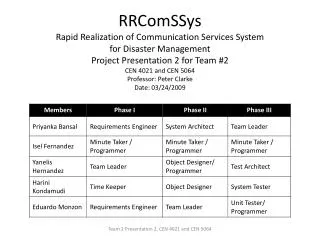
RRComSSysRapid Realization of Communication Services Systemfor Disaster Management Project Presentation 2 for Team #2 CEN 4021 and CEN 5064Professor: Peter ClarkeDate: 03/24/2009 Team 2 Presentation 2, CEN 4021 and CEN 5064
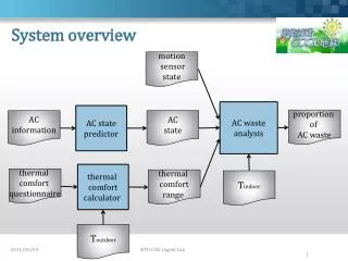
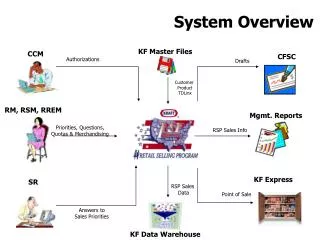
System Overview • Provides a domain-specific visual environment for the modeling of a Disaster Management communication service. • Allows the developer to capture relevant details from the customer before initiating the implementation. • Provides a generative architecture that will be transparent to developer. • Allows generating executable code from the communication schema specified. Team 2 Presentation 2, CEN 4021 and CEN 5064
System Requirements (I) • The system shall allow developers to successfully log-in into the system • The system shall allow developers to successfully log-out of the system • The system shall allow developers to create two-way video schemas using a graphical modeling tool • The system shall allow developers to create three-way voice schemas using a graphical modeling tool • The system shall allow developers to create two-way chat schemas using a graphical modeling tool Team 2 Presentation 2, CEN 4021 and CEN 5064
System Requirements (II) • The system shall allow developers to save communication schemas into the repository of models • The system shall allow users to load communication schemas from the repository of models • The system shall allow users to execute communication schemas by first transforming them into communication instances and validating them • The system shall allow developers to drop shapes in the process of creation of a communication model • The system shall allow developers to connect shapes in the process of creation of a communication model Team 2 Presentation 2, CEN 4021 and CEN 5064
Design Methodology – MDSD Team 2 Presentation 2, CEN 4021 and CEN 5064
Meta-model for CML - Communication Team 2 Presentation 2, CEN 4021 and CEN 5064
Meta-model for CML - Workflow Team 2 Presentation 2, CEN 4021 and CEN 5064
Software Architecture (I) • Pipe & Filter : Used in the modeling and code generation subsystems. • Classes involved in representing the G-CML and X-CML models are pipes. • Classes involved in doing the transformations of the XML files are filters. • Model View Controller : Used in the model execution subsystems. • Views are the multiple windows to enable the execution of a model • Model is the set of entities to represent the communication model. • Controller are the classes responsible for ensuring the flow of events. Team 2 Presentation 2, CEN 4021 and CEN 5064
Software Architecture (2) Team 2 Presentation 2, CEN 4021 and CEN 5064
UML Profile – Main Package Team 2 Presentation 2, CEN 4021 and CEN 5064
Class Diagram – Main Package (I) Factory Method Command Team 2 Presentation 2, CEN 4021 and CEN 5064
Class Diagram – Main Package (II) Singleton Team 2 Presentation 2, CEN 4021 and CEN 5064
Object Interaction (I) – State Machine Team 2 Presentation 2, CEN 4021 and CEN 5064
Object Interaction (2)-Drop and Connect Two Shapes Team 2 Presentation 2, CEN 4021 and CEN 5064
Object Interaction (3) - Execute Model Team 2 Presentation 2, CEN 4021 and CEN 5064
The End Thank you! Questions and Answers Team 2 Presentation 2, CEN 4021 and CEN 5064