Splice Detector Technologies: Model 1108 Keymark Register Control
Explore the benefits of the Model 1108 Register Control System for accurate in-register processing of web materials. Enhance your production quality with reliable mark detection and correction capabilities.

Splice Detector Technologies: Model 1108 Keymark Register Control
E N D
Presentation Transcript
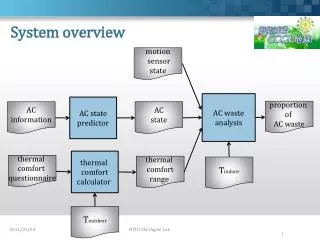
System Overview Model 1108 Keymark Register Control Technology Bruce T. Dobbie
Mission Statement Splice Detector Technologies is a designer and manufacturer of high speed splice, tearout, missing ply and web break detection equipment and related products. We are committed to the industry and our customers that depend on us to ensure that quality is maintained at the highest possible level. We are dedicated to increasing customer satisfaction, continuously improving our products and services, and providing opportunities for our employees to achieve their maximum potential.
Product: Keymark Register Control http://www.splicedetector.net/splicedetector_products/cut_to_register.html or http://www.splicedetector.com/splicedetector_products/cut_to_register.html FOR MORE INFO...
Overview of Benefits gained The Model 1108 Register Control Computer is designed for integration with existing production equipment to ensure in-register processing of web materials. It is suitable for many types of processing, printing, and converting applications requiring material registration or similar process controls. The most important aspect of registration control is reliable detection of the registration mark. Our Model 1108 is compatible with a wide range of illumination, sensing, and signal processing technologies for detection of any type of mark including keyed, non-keyed, printed and watermarks.
Methodology • The Model 1108 Register Control System controls the printing, embossing or knife of a cutter to insure continuous in‑register processing of web materials. The registration mark (watermarked, printed, etc.) is photo-electronically detected in the moving web by a detection head which utilizes an detector in conjunction with a lighting technique which enhances the visibility of the mark. In this presentation we will use the example of registering a watermark in a paper sheet cutting operation.
Methodology • Reliable detection to a registration mark (keymark) is the most important aspect of registration control. Once the registration mark is detected, it may be compared to the anticipated future function to determine whether the material is being processed in‑register.
Methodology • In a paper sheeting operation, for example, the future cut‑line is an imaginary cut‑line the Register Control Computer calculates in relationship to the detection head used to detect the registration mark. Because the mark must be detected sufficiently ahead of the cutter knife to maximize knife correction time available, the future cut‑line must be calculated to offset the difference between the knife and the detection head.
Methodology • The future cut‑line is determined by electronically encoding the movement of the web in relationship to the rotation of the cutter knife. The future cut‑line is then positionally synchronized with the detection head by mathematically accounting for the distance between the detection head and the cutter knife in terms of the sheet length being cut. Thus, the future cut‑line is a signal which occurs when the location of a future cut‑line passes under the detection head. This signal is then logically compared against the detection of the registration mark to determine if the cutter is in synchronization or needs correction.
Methodology • When the location of the future cut‑line has been determined in relationship to the registration mark (ahead, behind, in‑sync); an appropriate signal will be sent to the drive circuitry of the correction motor to insure that the actual cut‑line falls at the registration mark. The correction motor is used to advance or retard the variable knife drive, such as a PIV or similar. A speed correction circuit and related tachometer have been supplied to compensate for variation in processing speeds.
Features and Benefits • Register module: This processing board is used to generate the future cut‑line, compare the registration mark location to the future cut‑line and then determine whether the cutter knife needs to be advanced, retarded or held constant. • Power module:This rack-mounted assembly contains the circuitry and relays used to switch polarity of the correction motor drive voltage. By controlling the polarity of the motor drive circuitry the direction of rotation of the correction motor may be controlled; thus, enabling an advance or retard of the cutter knife. The Motor Control Unit also drives the in-sync, advance and retard indicator lamps on the front of the control cabinet.
Features and Benefits • Logic module: This rack mounted printed circuit board receives the knife control command from the Register Control Unit and outputs a command to the Motor Control Unit. When a command has been output to the Motor Control Unit, the Logic Control Unit inhibits all other signals to the Motor Control Unit. • Sheet length module: This rack mounted, printed circuit board is used to set the desired sheet length so that the future cut-line can be properly determined.
Features and Benefits • Motor control module: This rack mounted assembly contains the circuitry and relays used to switch polarity of the correction motor drive voltage. By controlling the polarity of the motor drive circuitry, the direction of rotation of the correction motor may be controlled; thus, enabling an advance or retard of the cutter knife. The Motor Control Unit also drives the in‑sync, advance and retard indicator lamps on the front of the control cabinet. • SCR module: The SCR Control Unit is a rack mounted printed circuit board which regulates the voltages used for driving the correction motor. The SCR Control Unit receives signals from the Analog Control Unit which affects the SCR output in relationship to web processing speed. Thus, the SCR Control Unit is used to vary the speed at which correction is performed.
Features and Benefits • Watermark Detection Head The Detection Head is used to detect the registration mark in the web. There are two types of heads depending on the application. Each sensor is housed in a fabricated aluminum housing containing either a row of photo-transistors or a CCD line scan chip. The aperture is used to enhance detection of the registration mark by reducing the amount of formation noise detected by the phototransistors; improving the signal‑to‑noise ratio for detection of the mark.
Features and Benefits • When a registration mark passes through the field‑of‑view of the Detection Head, the intensity of the infra‑red light transmitted through the web is distinctly altered. The distinct change in the infra‑red transmission will result in an analog signal which is amplified and converted to a digital pulse before being output to the Registration Module in the Control Cabinet.
Features and Benefits • Lamp Sensing Unit The infra‑red light used for the detection of the registration mark is produced by a 12 volt filament lamp driven with direct current and housed in an aluminum fabricated Light Source Assembly. The assembly is located opposite the Detection Head on the other side of the web of material.
Features and Benefits • Meets quality initiative and ISO requirements. • Detection 24/7 without the need for operational intervention. • Eliminate the need for manual inspections.
Applications • Watermark on Sheeters • Wide Format Printing • Rotogravure • Offset • Flexo and screen printing
Specifications • Registration Accuracy: 1/16" (1.5 mm) or Less From Registration Mark • Marks Detected: Non-Keyed Watermarks, Keyed Watermarks, Printed Watermarks, and Other Marks Subject to Tests • Maximum Web Speed: Unlimited • Dimensions: Rack Mounted • Ambient Temperature: 40° to 160° F (4° to 70° C) • Power: 110/220 or 220/240 VAC50/60 Hz Single Phase
References • For reliability; large, medium and small companies turn to RKB for their keymark register control requirements.
Related Websites • http://www.rkbopto.com • Syracuse, New York, United States • http://rkb.chinapaper.net • Suzhou, Jiangsu, China • http://www. fioproin.it • Milan, Italy • http://www.swallowmachinery.com/ • Meltham, Holmfirth, United Kingdom • http://www.quality2process.com • Delden, Netherlands • http://www.splicedetector.net / www.hole-detection.com / www.webinspection.us / www.splicedetector.com • Syracuse, New York, United States