Optimization of LDO-based Power Distribution Design Under Worst-Case Loading Conditions
This paper presents a comprehensive approach to designing Low Dropout Regulators (LDO) for power distribution networks (PDN) under worst-case loading scenarios. The study introduces a methodology based on poles/zeros to analyze and optimize LDO performance, focusing on minimizing voltage drop and managing power delivery. Key findings include insights on managing noise response, achieving finer grain power management, and addressing challenges in power consumption and stability. The experimental results confirm that the proposed optimization meets voltage drop requirements while ensuring adequate power delivery under challenging conditions.

Optimization of LDO-based Power Distribution Design Under Worst-Case Loading Conditions
E N D
Presentation Transcript
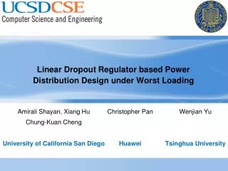
Christopher Pan • Huawei Wenjian Yu • Tsinghua University Linear Dropout Regulator based Power Distribution Design under Worst Loading Amirali Shayan, Xiang Hu Chung-Kuan Cheng University of California San Diego
Agenda • Introduction and Motivation • LDO based PDN Design under Worst Loading • Worst case current synthesis • Poles/Zeros based Methodology • Experimental Results and Trade offs • Conclusion Remarks
Introduction • LDO design will enable: • Localized on die regulation • Relax off chip impedance • Power saving • Finer grain power management • LDO design challenges • Power consumption • Area of the power MOSFET • Stability of the feedback loop • Physical design
Integrated On-die LDO Shortens the PDN loop LDO based PDN Optimization under Worst Loading Virtually eliminate 1st and 2nd droops Original Optimize Package With LDO |z| Freq Bulk caps Package VR RPCB RPKG RDIE TR Die MB caps LDO VRM RDIE TR RPCB RPKG LDO Motherboard Adv #1: Better dynamic power management through reduced response time Adv #2: Maintain low package cost while provide adequate power delivery Power saving opportunity
LDO-PDN Model of Design (1) • Operation region of the power MOSFET depends on the Vds=Vext-Vout comparison with (Vgs-Vth). • In our analysis, power MOSFET is in the linear region.
Problem Formulation • P = LDO Power • C = Decoupling Capacitor • P0 = Power limit • I peak = Peak loading current of functional block • Vmax = Worst voltage drop based on rogue wave • Z LDO-PDN = impedance profile of ldo-pdn
LDO-PDN Output Impedance • impedance zero = • Z1=-2.0011 x 1e9 • Z4,5= -0.0107 ± 0.0156i × 1e9 • impedance pole = • p1=-1.8177 • p4,5= -0.0125 ± 0.0142i × 1e9 • Impedance k= 0.0091
“Rogue Wave” Phenomenon • Worst-case noise response: The maximum noise is formed when a long and slow oscillation followed by a short and fast oscillation. • Rogue wave: In oceanography, a large wave is formed when a long and slow wave hits a sudden quick wave. High-frequency oscillation corresponds to the resonance of the 1st stage Low-frequency oscillation corresponds to the resonance of the 2nd stage
Ideal Worst-Case PDN Noise • Problem formulation I • PDN noise: • Worst-case current [Xiang ’09]: Zero current transition time. Unrealistic!
Algorithm for Vector-based Rogue Wave Generation for i = 0 to N-window_size Begin sum each current peak of current pattern(i, i+window_size - 1) End sorted_list_des = sorting the sum of the intervals of current peak descending sorted_list_asc = sorting the sum of the intervals of current peak ascending //here is for worst-case calculating for i = 0 to N-window_size and i is increased by window_size //N is the size of impulse_reseponse if impulse_response(i) > 0 current_list = sorted_list_des else current_list = sorted_list_asc End for j = 0 to M - window_size + 1 //M is the size of current pattern idx_current = current_list(j) tmp_val = convolution of impulse_response(i, i + window_size - 1) and current_pattern(idx_current, idx_current + window_size -1) if tmp_val > max_val max_val = tmp_val max_current(i, i+window_size -1) = current_pattern(idx_current, idx_current + window_size - 1) else break end end //end of for j end //end of for i • Complexity of algorithm = • N= Impulse response size • m= Current windows size
Rogue-wave Synthesis Resolution Window Sensitivity to Vmax • For the rest of analysis, window resolution = 3nsec is chosen.
Vmax LDO-PDN Voltage Drop (Overshoot) • Overshoot is a main concern for: • Reliability of devices • Hold margins
Vmin LDO-PDN Voltage Drop (Undershoot) • undershoot is a main concern for: • Functional failures • Optimum Configuration: • Optimal Decap = 350pF • Optimal Power= 20uW • Noise = ~10mV
Conclusion and Summary • Introduced a design flow for worst case loading based on LDO poles and zeros. • Proposed an optimization based on the step response and rogue wave in LDO system. • Analyzed LDO power and decap area trade off in the LDO based system. • Experimental result show the target voltage drop budget will be met under worst loading with optimum LDO power and decoupling value.