Functional Analysis and Allocation
Functional Analysis and Allocation. Wally Tubell and David Swinney Defense Acquisition University March 4, 2009. Functional Analysis and Allocation (FA/A). Describe FA/A Distinguish between functional analysis, functional allocation , and functional architecture

Functional Analysis and Allocation
E N D
Presentation Transcript
Functional Analysis and Allocation Wally Tubell and David SwinneyDefense Acquisition University March 4, 2009
Functional Analysis and Allocation (FA/A) • Describe FA/A • Distinguish between functional analysis, functional allocation, and functional architecture • Introduce basic tools of FA/A
Systems Engineering Process PROCESS INPUT Systems Analysis and Control Requirements Analysis (Balance) Requirements Loop Functional Analysis/ Allocation Design Verification Loop Loop Synthesis PROCESS OUTPUT
Systems Engineering Process PROCESS INPUT TechnicalManagementProcesses Systems Analysis and Control Requirements Development Requirements Loop Logical Analysis Design Verification Loop Loop Design Solution PROCESS OUTPUT
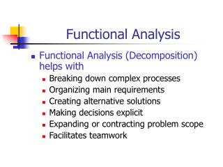
FA/A Definition • Examination of a function to identify all sub-functions necessary to accomplish that function • Identification of functional relationships and interfaces • Capturing functional relationships in a Functional Architecture
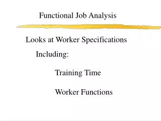
FA/A Main Tasks • Analyze Functions • Provide functional descriptions • Allocate performance • Establish technical architecture
Functional Analysis/Allocation • Decompose higher functions • Develop functional descriptions • Allocate performance from higher to lower functions • Perform Technical Architecture analysis What must the system do? To what extent must the function perform? Identification of standards and interface specifications.
Marine Troop Transport Requirement Practical Example
Marine Troop Transport Requirement • The Marine Corps has a requirement to transport troops in squad level units a distance of 50 km within 90 minutes. The troops must be combat-ready and able to travel over land ranging from desert to arctic terrain. • Throughout the trip, the vehicle must be able to communicate with headquarters, and the internal vehicle temperature must be maintained between 60° and 80°F.
Stakeholder Requirements Definition • Whatis the system supposed to do? • Wherewill the products of the system be used? • Under whatconditionswill the products be used? • Howoften?How long? • Whowill use the products of the system?
Requirements Analysis: Marine Troop Transport • Transport personnel • Squad level units • 50 km • 90 minutes • Combat gear • Traverse sand, ice, and snow • Communication with HQ • 60º-80º F Questions • How many troops in a squad? • How much equipment/gear? • Out and back or one-way trip? • Day and night? Weather? • Who will operate transporter?
Functional Analysis (Logical Analysis) • Analyzefunctions • Decompose higher level functions to lower level functions • Allocateperformance requirements to the functions This step answers the question: “HOW?” using “Action Verbs”
Functional Analysis: Marine Troop Transport Which action verbs describe the requirements?
Functional Analysis: Marine Troop Transport COMMUNICATE CONTROL TEMP TRANSPORT
Functional Analysis: Marine Troop Transport COMMUNICATE CONTROL TEMP TRANSPORT What ‘sub’ functions make up the “Transport” system level function?
Functional Analysis: Marine Troop Transport STOP START COMMUNICATE CONTROL TEMP TRANSPORT LOAD MOVE UNLOAD The start of a “Functional Architecture”
Functional Allocation: Marine Troop Transport STOP START 90 min TRANSPORT LOAD MOVE UNLOAD 10 min 2 min 72 min 1 min 5 min • Allocation of requirements, i.e., “within 90 minutes” • “Derived” requirements, i.e., “required speed” 42 Km/Hr • What tradeoffs could be made?
Requirements Loop • Ensureall requirementsare covered by at least one function • Ensureall functionsare justified by a valid requirement (no unnecessary duplication)
Functional Analysis: Marine Troop Transport TRANSPORT FUNCTION: LOAD START MOVE STOP UNLOAD REQUIREMENT: Requirements Traceability Matrix (Stakeholder Requirements to Functional Architecture)
Functional Analysis: Marine Troop Transport X X X X X X X X X X X X X X X X X X X TRANSPORT FUNCTION: LOAD START MOVE STOP UNLOAD REQUIREMENT: Transport personnel 50 km in 90 minutes Transport gear Traverse sand Traverse ice Traverse snow
Design Solution • Define the physical architecture • Each part must perform at least one function • Some parts may perform more than one function What performs the function(s)? NOUNS (hardware and/or software elements)
Design Solution: Marine Troop Transport VEHICLE ENGINE BODY WHEELS BRAKES RADIO Seats Hatch Heater Cooler Physical Architecture
Design Loop • Ensureall functionsare covered by at least one hardware or software element • Ensure all elements of physical architectureare justified by a valid functional requirement (no unnecessary duplication)
Design Solution: Marine Troop Transport X X X X X X X X X X X X X BODY DOOR SEATS HEATER COOLER LOAD START MOVE STOP UNLOAD CONTROL TEMP. ENGINE WHEELS BRAKES RADIO FUNCTION TRANSPORT COMMUNI- CATE Verbs and Nouns must all be covered (Crosswalk of functional and physical architectures)
Challenges of FA/A • Warfighter not continuously involved • Unknown or undefined requirements • Changing requirements over time • Competing / Conflicting Requirements • Changing technology (e.g. standards, interfaces, etc) • Lack of understanding of technical issues • Unrealistic budgets, schedules, or technical requirements • Lack of effort
FA/A Documentation Tools • Functional Flow Block Diagrams • Timeline Sheets • Requirements Allocation Sheet • Requirements Traceability Matrix
Other Tools • Functional Flow Block Diagram (FFBD) • Time Line Analysis • Requirements Allocation Sheet
Functional Flow Block DiagramTraceability & Indenture 6.0 5.0 3.0 2.0 1.0 4.0 Top Level 1st Level 2nd Level 2.6 2.8 1.6 1.1 1.2 1.3 1.7 2.7 1.4 1.5 1.5.6 1.5.7 1.4.1 1.4.2 1.4.3 1.4.6 1.4.7 1.4.4 1.4.5
Functional Flow Block Diagram - Example Ref 1.6, Provide Guidance Functional Title/Description Summing Gate Function Number 1.6.2 Go Flow 1.6.1 1.6.6 1.6.5 G • 1.3 • Ref • 1.7.1 • Ref & • & Parallel Functions 1.6.3 G • OR 1.6.7 • 1.7.4.2 • Ref • OR Alternative Functions • 1.5.7 • Ref 1.6.8 1.6.4 Leader Note No Go Flow Sys. Malf. Ancillary Function 2nd Level Abbreviations/Notes: Flow Level Designator Functional Flow Block Diagram Format “&” / ”AND” Gate: Parallel Functions “OR” Gate: Alternate Functions Title Block & Diagram No.
Functional Flow Block Diagram / 1 Function block: Each function on diagram should be separate and be represented by single box (solid line). Each function needs to stand for definite, finite, discrete action to be accomplished by system elements. Function numbering: Each level should have consistent number scheme and reflect function origin. (e.g. top level - 1.0, 2.0, 3.0, etc; first indenture (level 2) - 1.1, 1.2, 1.3, etc; second indenture (level 3) - 1.1.1, 1.1.2, 1.1.3, etc) Functional reference: Each diagram should contain a reference to other functional diagrams by using a functional reference (function # in brackets). Flow connection: Lines connecting functions should only indicate function flow and not a lapse in time or intermediate activity.
Functional Flow Block Diagram / 2 Flow direction: Diagrams should be laid out so that the flow direction is generally from left to right (top to bottom). Summing gates: A circle is used to denote a summing gate and is used when AND/OR is present. AND is used to indicate parallel functions and all conditions must be satisfied to proceed. OR is used to indicate that alternative paths can be satisfied to proceed (may be exclusive or inclusive). GO and NO-GO paths: Gand bar G (G) are used to denote go and no-go conditions. These symbols are placed adjacent to lines leaving a particular function to indicate alternative paths.
Timeline Analysis Function 3.1 Establish & Maintain Vehicle Readiness T-35 Hrs to T-2 Hrs Function Hours Number Name 35 30 25 20 15 10 5 4 3 2 3.1.1 Provide Ground Power 3.1.2 Provide Vehicle Air Conditioning 3.1.3 Install & Connect Batteries 2.5 3.1.4 Install Ordnance 7.5 3.1.5 Perform Voltage Checks & Connect Ordnance 2.5 3.1.6 Load Fuel Tanks 7.5 3.1.7 Load Oxidizer Tanks 7.5 3.1.8 Activate Guidance System 2.5 3.1.9 Establish Propulsion Flight Pressure 1.0 3.1.10 Telemetry System “On” 2.5 3.1.11 Perform Tracking/Range Safety Checks 0.5 3.1.12 Perform Vehicle Verification 1.5
Requirements Allocation Sheet Function Number & NamePerformance Requirements / Constraints 1.0 Accomplish Mission 1.1 Position Vehicle Strategic position: remote and protected. Carrier: tracked vehicle. 1.1.1 Receive move order 1.1.2 Drive to Location Speed: Up to 70 kph over unimproved roads. Swim Capability: 5 knots. Fuel Requirements: for 350 kilometers, cruising at 50 kph. Crew Provisions: Food and water for crew for 1 week. Crew Protection: Against small arms fire to within 8 km of FLOT. 1.1.3 Extend Hydraulic Feet Time: 5 minutes 1.1.4 Remove Missile Shrouds Time: 1 minute 1.1.5 Start Electrical Generators Time: 2 minutes 1.1.6 Establish Telecommunications Time: 2 minutes 1.1.7 Hold Alert Conditions 1.2 Launch Missile Missile Parameters Range: 30-350 kilometers Weight: 2500 kg (Nuclear); 2700 kg (HE) Length: 8 meters Diameter: 0.8 meter (less fins)
Trace Requirements to Functional Architecture X X X X X X X X X X X X X X X X X X X TRANSPORT FUNCTION: LOAD START MOVE STOP UNLOAD REQUIREMENT: Transport personnel 50 km in 90 minutes Transport gear Traverse sand Traverse ice Traverse snow
Functional Architecture to Physical Architecture X X X X X X X X X X X X X BODY DOOR SEATS HEATER COOLER LOAD START MOVE STOP UNLOAD CONTROL TEMP. ENGINE WHEELS BRAKES RADIO FUNCTION TRANSPORT COMMUNI- CATE
Summary • Description of Functional analysis and allocation • Differences between functional analysis, functional allocation, and functional architecture • Common tools of FA/A