Atomic Emission Spectroscopy
Atomic Emission Spectroscopy. Atomic Emission Spectroscopy.

Atomic Emission Spectroscopy
E N D
Presentation Transcript
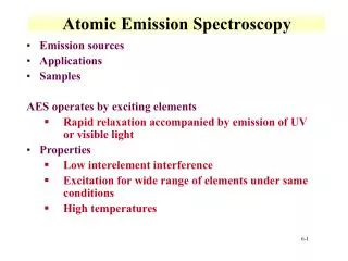
Atomic Emission Spectroscopy Atomic emission spectroscopy (AES), in contrast to AAS, uses the very high temperatures of atomization sources to excite atoms, thus excluding the need for lamp sources. Emission sources, which are routinely used in AES, include plasma, arcs and sparks, as well as flames. We will study the different types of emission sources, their operational principles, features, and operational characteristics. Finally, instrumental designs and applications of emission methods will be discussed.
Plasma Sources The term “plasma” is defined as a homogeneous mixture of gaseous atoms, ions and electrons at very high temperatures. Two types of plasma atomic emission sources are frequently used: • Inductively coupled plasma • Direct current plasma
Inductively Coupled Plasma (ICP) A typical ICP consists of three concentric quartz tubes through which streams of argon gas flow at a rate in the range from 5-20 L/min. The outer tube is about 2.5 cm in diameter and the top of this tube is surrounded by a radiofrequency powered induction coil producing a power of about 2 kW at a frequency in the range from 27-41 MHz. This coil produces a strong magnetic field as well.
Ionization of flowing argon is achieved by a spark where ionized argon interacts with the strong magnetic field and is thus forced to move within the vicinity of the induction coil at a very high speed. A very high temperature is obtained as a result of the very high resistance experienced by circulating argon (ohmic heating). The top of the quartz tube will experience very high temperatures and should, therefore, be isolated and cooled.
This can be accomplished by passing argon tangentially around the walls of the tube. A schematic of an ICP (usually called a torch plasma) is shown below:
The torch is formed as a result of the argon emission at the very high temperature of the plasma. The temperature gradients in the ICP torch can be pictured in the following graphics:
The viewing region used in elemental analysis is usually about 6000 oC, which is about 1.5-2.5 cm above the top of the tube. It should also be indicated that argon consumption is relatively high which makes the running cost of the ICP torch high as well. Argon is a unique inert gas for plasma torches since it has few emission lines. This decreases possibility of interferences with other analyte lines.
Sample Introduction There are several methods for sample introduction; the most widely used is, of course, the nebulization of an analyte solution into the plasma. However, other methods, as described earlier, are fine where vapors of analyte molecules or atom from electrothermal or ablation devices can be driven into the torch for complete atomization and excitation. For your convenience, sample introduction methods are summarized here again:
Samples in Solution 1. Pneumatic Nebulizers Samples in solution are usually easily introduced into the atomizer by a simple nebulization, aspiration, process. Nebulization converts the solution into an aerosol of very fine droplets using a jet of compressed gas. The flow of gas carries the aerosol droplets to the atomization chamber or region.
Ultrasonic Nebulizers In this case samples are pumped onto the surface of a piezoelectric crystal that vibrates in the kHz to MHz range. Such vibrations convert samples into homogeneous aerosols that can be driven into atomizers. Ultrasonic nebulization is preferred over pneumatic nebulization since finer droplets and more homogeneous aerosols are usually achieved. However, most instruments use pneumatic nebulization for convenience.
Electrothermal Vaporization An accurately measured quantity of sample (few mL) is introduced into an electrically heated cylindrical chamber through which an inert gas flows. Usually, the cylinder is made of pyrolytic carbon but tungsten cylinders are now available. The vapors of molecules and atoms are swept into the plasma source for complete atomization and excitation.
Hydride Generation Techniques Samples that contain arsenic, antimony, tin, selenium, bismuth, and lead can be vaporized by converting them to volatile hydrides by addition of sodium borohydride. Volatile hydrides are then swept into the plasma by a stream of an inert gas.
Introduction of Solid Samples A variety of techniques were used to introduce solid samples into atomizers. These include: 1. Conductive Samples If the sample is conductive and is of a shape that can be directly used as an electrode (like a piece of metal or coin), that would be the choice for sample introduction in arc and spark techniques. Otherwise, powdered solid samples are mixed with fine graphite and made into a paste. Upon drying, this solid composite can be used as an electrode. The discharge caused by arcs and sparks interacts with the surface of the solid sample creating a plume of very fine particulates and atoms that are swept into the plasma by argon flow.
Laser Ablation Sufficient energy from a focused intense laser will interact with the surface of samples (in a similar manner like arcs and sparks) resulting in ablation. The vapors of molecules and atoms are swept into the plasma source for complete atomization and excitation. Laser ablation is becoming increasingly used since it is applicable to conductive and nonconductive samples.
The Glow Discharge Technique The technique is used for sample introduction and atomization as well. The electrodes are kept at a 250 to 1000 V DC. This high potential is sufficient to cause ionization of argon, which will be accelerated to the cathode where the sample is introduced. Collision of the fast moving energetic argon ions with the sample (cathode) causes atomization by a process called sputtering. Samples should thus be conductive to use the technique of glow discharge. The vapors of molecules and atoms are swept into the plasma source for complete atomization and excitation by flowing argon. However, nonconductive samples were reported to be atomized by this technique where they were mixed with a conductor material like graphite or powdered copper.
Plasma Appearance and Spectra A plasma torch looks very much like a flame but with a very intense nontransparent brilliant white color at the core (less than 1 cm above the top). In the region from 1-3 cm above the top of the tube, the plasma becomes transparent. The temperatures used are at least two to three orders of magnitude higher than that achieved by flames which may suggest efficient atomization and fewer chemical interferences.
Ionization in plasma may be thought to be a problem due to the very high temperatures, but fortunately the large electron flux from the ionization of argon will suppress ionization of all species.
The Direct Current Plasma (DCP) The DCP is composed of three electrodes arranged in an inverted Y configuration. A tungsten cathode resides at the top arm of the inverted Y while the lower two arms are occupied by two graphite anodes. Argon flows from the two anode blocks and plasma is obtained by momentarily bringing the cathode in contact with the anodes. Argon ionizes and a high current passes through the cathode and anodes.
It is this current which ionizes more argon and sustains the current indefinitely. Samples are aspirated into the vicinity of the electrodes (at the center of the inverted Y) where the temperature is about 5000 oC. DCP sources usually have fewer lines than ICP sources, require less argon/hour, and have lower sensitivities than ICP sources. In addition, the graphite electrodes tend to decay with continuous use and should thus be frequently exchanged. A schematic of a DCP source is shown below:
A DCP has the advantage of less argon consumption, simpler instrumental requirements, and less spectral line interference. However, ICP sources are more convenient to work with, free from frequent consumables (like the anodes in DCP’s which need to be frequently changed), and are more sensitive than DCP sources.
Advantages of Plasma Sources • No oxide formation as a result of two factors including • Very high temperature • Inert environment inside the plasma (no oxygen) 2. Minimum chemical interferences 3. Minimum spectral interferences except for higher possibility of spectral line interference due to exceedingly large number of emission lines (because of high temperature)
4. Uniform temperature which results in precise determinations 5. No self-absorption is observed which extends the linear dynamic range to higher concentrations 6. No need for a separate lamp for each element 7. Easily adaptable to multichannel analysis
Plasma Emission Instruments Three classes of plasma emission instruments can be presented including: 1. Sequential instruments In this class of instruments a single channel detector is used where the signal for each element is read using the specific wavelength for each element sequentially. Two types of sequential instruments are available:
Linear sequential scan instruments where the wavelength is linearly changed with time. Therefore, the grating is driven by a single speed during an analysis of interest b. Slew scan instruments where the monochromator is preset to provide specific wavelengths; moving very fast in between wavelengths while moving slowly at the specific wavelengths. Therefore, a two-speed motor driving the grating is thus used.
Radial vs. Axial Viewing Radial – traditional side view, better for concentrated samples. Axial – direct view into plasma, lower sensitivity, shifts detection range lower.
Sequential vs. multichannel • Sequential instrument • PMT moved behind aperture plate, • or grating + prism moved to focus new l on exit slit • Pre-configured exit slits to detect up to 20 lines, slew scan • characteristics • Cheaper • Slower • Multichannel instrument • Polychromators (not monochromator) - multiple PMT's • Array-based system • charge-injection device/charge coupled device • characteristics • Expensive ( > $80,000) • Faster
Slew scan spectrometer • Two slew-scan gratings • Two PMTs for VIS and UV • Most use holographic grating
2. Multichannel Instruments This class of instruments is also referred to as simultaneous instruments in which all signals are reported at the same time using two types of configurations:
a. Polychromators Multiple detectors, usually photomultiplier tubes are used. Beams of radiation emerging from the grating are guided to exit slits (each representing the wavelength of a specific element) are focused at several PMTs for detection. Detection, thus, takes place simultaneously
Detectors Grating
b. Array-based systems This multichannel type instrument uses a multichannel detector like a charge injection device or a charge-coupled device. Diffracted beams from a grating pass through a prism where further resolution of diffracted beams takes place by a prism. The prism will disperse the orders of each diffracted beam. The multichannel detector can also be a linear photodiode array as in the figure below:
Diode Array Detector Grating
CCD or CID Detector Grating
3. Fourier transform instruments (FT) Instruments in which the signal is coded will need a decoding mechanism in order to see the signal. FT is a very common technique for decoding time domain spectra. In such instruments, the detector records the change of signal with time, which is practically not useful. However, Fourier transformation of the time domain signal yield a frequency domain spectrum, which is the usual signal, obtained by conventional methods. Instruments that rely on decoding a coded signal is also said to have a multiplex design.
Applications of Plasma Sources 1. Since plasma sources result in a very large number of emission lines, these sources can be used for both qualitative and quantitative analysis. 2. The signal obtained from plasma sources is stable, has a low noise and background, as well as freedom from interferences. 3. Requires sample preparation similar to AAS
4. Plasma sources are usually best suited for operation in the ultraviolet region, therefore, elements having emission lines below 180 nm (like B, P, S, N, and C) can be only analyzed under vacuum since air components absorb under 180 nm. Also, alkali metals are difficult to analyze since their best lines under plasma conditions occur in the near infrared. 5. An analytical emission line can easily be located but will depend on the other elements present since spectral line interferences are encountered in plasma sources due to the very high temperatures used.
6. Linear calibration plots are usually obtained but departure from linearity is observed at high concentrations; due to self absorption as well as other instrumental reasons. An internal standard is often used in emission methods to correct for fluctuations in temperature as well as other factors. The calibration plot in this case is a plot between the concentration of analyte and the ratio of the analyte to internal standard signal. The internal standard is a substance that is added in a constant amount to all samples, blanks, and standards; therefore it must be absent from initial sample matrix. The internal standard should have very close characteristics (both chemically and physically) to analyte.
Elements by ICP-AES Different elements have different emission intensities. Alkalis (Na, K, Rb, Cs) are weakly emitting. Alkaline Earths (Be, Mg, Ca, Sr, Ba ) are strongly emitting.