Atomic Absorption & Emission Spectroscopy
Atomic Absorption & Emission Spectroscopy. Chapter 5. Sub Topics. Introduction to Atomic Spectroscopy. Atomic Absorption Spectroscopy AAS. Atomic Emission Spectroscopy AES. Interferences and Comparisons. Atomic Absorption and Emission Spectroscopy. What is it used for?

Atomic Absorption & Emission Spectroscopy
E N D
Presentation Transcript
Sub Topics Introduction to Atomic Spectroscopy Atomic Absorption Spectroscopy AAS Atomic Emission Spectroscopy AES Interferences and Comparisons
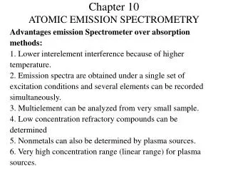
Atomic Absorption and Emission Spectroscopy What is it used for? Study of trace metals in the environment Examples: • Contamination of water • Food stuffs • Petrol products • Quality control Qualitative and Quantitative method for >70 elements with detection levels in ppm/ppb range Fast and convenient with high selectivity
Three Types Done in the Gas Phase Why is this significant? No vibrational or rotational energy levels, only electronic transitions Therefore spectra made of quantised spectral lines Spectral ranges of interactions? 180 – 800 nm (UV-Vis) Where is electromagnetic radiation absorbed / emitted in each spectroscopy?
Spectrum Related to Electronic Configuration(s)
Basic Instrumentation Requirements: Atoms / Ions in gas phase AES: No Radiation Source AAS: As Shown AFS: Radiation Source at 90’ to Detector
Atomisation Sample needs to be in gas phase Atomisation is therefore crucial Several ways: AES • Inductively Coupled Plasma (ICP) AAS • Flames • Electrothermal Atomizers Two Types of Atomisation Continuous Sample Continuously Introduced Discrete Sample introduced by syringe/autosampler
Sub Topics Introduction to Atomic Spectroscopy Atomic Absorption Spectroscopy AAS Atomic Emission Spectroscopy AAS Interferences and Comparisons
Process of Atomisation Nebulization Production of mist / spray Commonly used for solutions. Solids: Electric Spark or Laser
Example of Atomisation ProcessFlames Geometry of a Flame Different Fuels Different fuels give different temperatures Normal Flame Alkali/Alkaline Metals 1700-2400’C O2 or N2O Heavy Metals 2500-3100’C
Sample Introduction and Atomisation Pneumatic Nebulizer Continuous Achieved using Venturi Effect • Jet effect to form mist / spray
Interferences Any effect that changes signal from proper signal Blank Interferences Spectral Analyte (multiplicative) Interferences Physical (matrix) Chemical Ionisation
Spectral Interferences Independent of Analyte concentration From elements other than Analyte E.g. Na (285.28 nm) overlaps Mg (285.21)nm Can subtract blank Na spectrum Results in Line Broadening Spectral lines have finite widths, but determined by spectrometry properties Not needed to know different types
Sub Topics Introduction to Atomic Spectroscopy Atomic Absorption Spectroscopy AAS Atomic Emission Spectroscopy AES Interferences and comparisons
Inductively Coupled Plasma Plasma Atomisers Plasma is a conducting gaseous mixture containing cations and anions. Argon typically used for AAS Once Argon ions formed, can absorb enough power from external source to reach high temperatures so further ionisation can occur (T > 10,000 K) Power Sources DC Electric Powerful Radio Frequency (RF) Generators Powerful Microwave Frequency (MW) Generators (ICP) RF / ICP provide best advantage, sensitivity and freedom from interference DC Plasma cheaper and simpler
Inductively Coupled Plasma Three concentric quartz tubes End of torch is a RF induction coil which induces magnetic field Gases (Ar or N2) flow in outer tubes to cool torch. Stabilizes plasma. Torch is seeded with electrons using spark. H accelerates to high energy to ionise gases. White hot fireball formed (8000 – 10000 K)
Inductively Coupled Plasma Sample (from nebulizer, + Ar gas) is injected into it via central tube. Advantages Higher Excitation Temperature than any flame Lower detection limits Wide range of metals and non-metals Disadvantages Many Lines Initial and Running Costs Large! Other Points Long, Linear Calibration Curves (4-5 orders magnitude) Useful for both Atomic Spectroscopy and Mass Spectrometry
Comparison ICP vs DC ICP Advantages • Chemically inert environment • Unlike a flame (violent, highly reactive) • Temperature cross-section constant • Thin optical path • Reduces self-absorption • Calibration linear over large orders of concentration Disadvantages • Does not like organic solvents • Clogging due to carbon build up DC and other Plasma Sources Advantages • Less Argon Needed • Can cope with organic solvents • Less expensive • Less sensitive • Good Reproducibility Disadvantages • Useful for atoms, not ions • Good alignment of optics • Electrodes need to be replaced
Recap so far Need Light Source Flame most common source Elemental Analysis ICP Most common source
Some more equations Intensity is donated by Atomic absorption transmission is given by Therefore, with some higgery-pokery Absorbance is given by
Absorbance Characteristic Concentration The concentration in mg/L which gives 1% absorbance for a certain element Why? 1% absorbance = 99% transmission Log(1/0.99) = 0.0044
Requirements for Source Atomic Absorption Spectroscopy AAS • Narrow resonance line profile from lamp • Stable and reproducible output • Enough intensity for good S/N ratio • Durability • Easy Operation Hollow Cathode Lamp Good Choice!
Atomization AAS Flame Air or N2O combined with acetylene Eletrothemal Atomizer Graphite furnace Background Corrections may be required Chemical Interference Continuum Source Corrections Pulsed Hollow Cathode Lamp Corrections Zeeman Effect
Electrothermal Atomizers: Graphite Furnace AAS Drawbacks of AAS/AES/AFS in General Large volumes Poor efficiency nebulization Aqueous solutions required Electrothermal Atomizer: Graphite Furnace (AAS/AES only) Heated with inert purge gas All sample is atomized in confined space! Small volume in furnace with a syringe Programmed heating
GF-AAS Procedure • Introduce sample • 5-50 microlitres or solid • Add modifier • Drying • 110’C • Pyrolysis/Ashing • 300-1100’C • Evaporation of matrix? • Atomisation and measurement time resolved • 2000-3000’C • Clean out • Cool down Whole process takes milliseconds!
GF-AAS Interferences Corrections are needed Matrix Modifier Dual Lamp setup T selective programing Zeeman Correction
Zeeman Effect Correction Strong Magnetic Field splits degenerate spectral lines into several lines according to their Mj values, which have different polarization characteristics Example, Magnesium
Sub Topics Introduction to Atomic Spectroscopy Atomic Absorption Spectroscopy AAS Atomic Emission Spectroscopy AES Interferences and comparisons
Interferences Ionization Loss of atoms as ions – give completely different spectra Can be supressed by adding ionization suppressor (e.g. Cs) to sample and reference Chemical Key problem for AAS Formation of chemical species which prevent/promote dissociation, giving rise to depressed/enhanced signals Requires releasing/protective agents
Calibration Very Important Encompass range of expected values for samples Blank Triplicate to determine detection limit Standard addition method required for high matrix samples
Comparison What is less prone to spectral interferences? AAS AES Temperature affects signal more in? AES / AFS AAS Because ground state population is largest
Comparison Rank the following in Limit of Detection? AES, ICP-AES, AAS,GF-AAS, AFS AES>AFS>AAS>ICPAES>GF-AAS Rank the following in dynamic working range? AES, ICP-AES, AAS, GF-AAS, AFS ICP-AES>AFS>AES>AAS>GF-AAS
Other Comparisons AAS Ratio method removes systematic errors but sensitivity affected by difference in two large quantities ICP-AES and AFS can be multi element, less so than ASS AAS most cost effective, ICP-AES most versatile AFS good for vapour phase elements Cost of instrumentation ICP-AES>GF-AAS>AAS>AFS>AES