Download
1 / 10
450 likes | 1.69k Vues
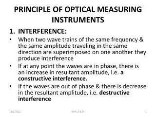
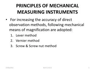
PRINCIPLES OF MECHANICAL MEASURING INSTRUMENTS. For increasing the accuracy of direct observation methods, following mechanical means of magnification are adopted: Lever method Vernier method Screw & Screw nut method. PRINCIPLES OF MECHANICAL MEASURING INSTRUMENTS (Cont..). Lever Method:

E N D
PRINCIPLES OF MECHANICAL MEASURING INSTRUMENTS • For increasing the accuracy of direct observation methods, following mechanical means of magnification are adopted: • Lever method • Vernier method • Screw & Screw nut method lec # 11 & 12
PRINCIPLES OF MECHANICAL MEASURING INSTRUMENTS(Cont..) • Lever Method: In fig.2.1 is shown the principle of simple magnifying lever (consisting of multiplying lever & a scale). The lever is supported on a knife edge support. When a distance ‘l’ is measured by the indicator the magnification ratio is given by: a/b = Reading on the scale/bsinα= a.α/bsinα Where α= angle of displacement corresponding to the measured distance l. lec # 11 & 12
PRINCIPLES OF MECHANICAL MEASURING INSTRUMENTS (Cont..) • Lever Method (cont..): It may be observed that the magnification ratio increases by increasing the displacement angle α. Thus for equal distance l there will be unequal displacement angle α, so that scales will have unequal divisions. lec # 11 & 12
PRINCIPLES OF MECHANICAL MEASURING INSTRUMENTS (Cont..) 1. Lever Method (cont..): To eliminate this, the angular measurement range of the system must be made relatively small. In this method the magnification is practically limited to 10:1 because of the greater friction involved on pivots & bearing of the system for greater magnification The friction can be reduced by means of specially designed pivots & bearings & making use of knife edges lec # 11 & 12
PRINCIPLES OF MECHANICAL MEASURING INSTRUMENTS 2. Vernier Method Principle: • In this method, a Vernier is used • It is an additional scale which is used in place of a pointer or indication line on the moveable member & it enables the main fixed scale to be read to a smaller value • Refer fig 2.2. if the graduation of the main scale are in cm & each is divided in 10mm, the readings taken by such a scale will be accurate within 1mm lec # 11 & 12
PRINCIPLES OF MECHANICAL MEASURING INSTRUMENTS 2. Vernier Method Principle: • If a sliding Vernier is provided , whose scale length equals 9mm but is divided into 10 equal divisions, the difference b/w the scale division of the vernier & that of the main scale will be (1.0 -9/10)=0.1mm • If the vernier scale is set so that its zero coincides with the zero line of the main scale, the first line on the vernier scale will be 0.1mm shorter than the corresponding line on the main scale . Therefore scale value of 0.1mm can be achieved by using a vernier lec # 11 & 12
PRINCIPLES OF MECHANICAL MEASURING INSTRUMENTS 2. Vernier Method Principle: • When the scale is to be read, the reading of the main scale is first taken upto the zero mark of the vernier then the reading of the vernier scale graduation that coincide with the division on the main scale is noted, which gives the fraction of the main scale graduation according to the scale value of the vernier • Vernier principle can be applied for increasing the accuracy of angular measurements lec # 11 & 12
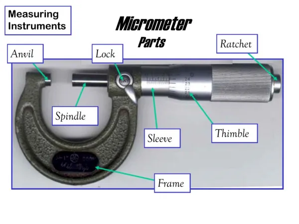
PRINCIPLES OF MECHANICAL MEASURING INSTRUMENTS 3. Screw & Screw-nut Method: • Refer Fig 3.3. The Screw & nut consists of the following: Fixed Frame: It has two contact members or anvils. One anvil is fixed & the other is moveable Moveable Anvil: It is provided with the threaded part & can be advanced by means of barrel nut Barrel nut: ThePeriphery of the barrel nut is graduated & its reading can be taken opposite to a fixed pointer Scale: The number of complete terms of the nut is indicated by means of a scale engraved on the plain part lec # 11 & 12
PRINCIPLES OF MECHANICAL MEASURING INSTRUMENTS 3. Screw & Screw-nut Method: • The scale should read zero when the anvils (fixe & moveable) are in contact. The readings of the scale give the distance b/w the end faces of the anvils • If p is the pitch of the screw thread & N is the total number of equal divisions on the barrel nut then the corresponding axial shift ‘a’ per movement of one division on the barrel nut is given as the scale value of the instrument by; a = p/N lec # 11 & 12
PRINCIPLES OF MECHANICAL MEASURING INSTRUMENTS 3. Screw & Screw-nut Method: • Normally when the pitch , p=0.5mm the barrel will be divided to 50 divisions. In that case, each division will read 0.5/50=0.01mm. In this case the main scale must be graduated in 0.5 mm, which is equal to the pitch of the screw thread • When the pitch p=1mm, the barrel will be divided to 100 divisions such that each division reads 0.01mm. The scale can be divided in millimeters • When a vernier is employed to read the barrel division, the accuracy can be increased 10 times so that it is possible to obtain a reading to the nearest 0.001mm lec # 11 & 12