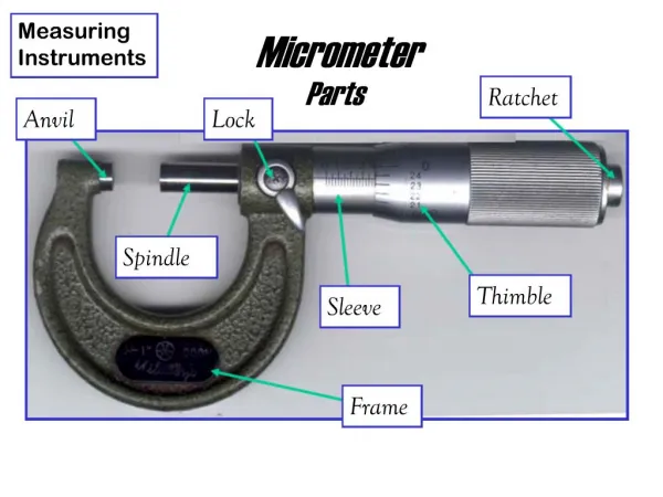
MEASURING INSTRUMENTS
MEASURING INSTRUMENTS. By: Sajid Hussain Qazi. MEASURING INSTRUMENTS. “The device used for comparing the unknown quantity with the unit of measurement or standard quantity is called a Measuring Instrument.” OR

MEASURING INSTRUMENTS
E N D
Presentation Transcript
MEASURING INSTRUMENTS By: SajidHussainQazi
MEASURING INSTRUMENTS “The device used for comparing the unknown quantity with the unit of measurement or standard quantity is called a Measuring Instrument.” OR “An instrument may be defined as a machine or system which is designed to maintain functional relationship between prescribed properties of physical variables & could include means of communication to human observer.”
CLASSIFICATION OF INSTRUMENTS Electrical instruments may be divided into two categories, that are; • Absolute instruments, • Secondary instruments. - Absolute instruments gives the quantity to be measured in term of instrument constant & its deflection. - In Secondary instruments the deflection gives the magnitude of electrical quantity to be measured directly. These instruments are required to be calibrated by comparing with another standard instrument before putting into use.
CLASSIFICATION OF INSTRUMENTS Electrical measuring instruments may also be classified according to the kind of quantity, kind of current, principle of operation of moving system. CLASSIFICATION OF SECONDARY INSTRUMENTS • Secondary instruments can be classified into three types; i. Indicating instruments; ii. Recording instruments; iii. Integrating instruments.
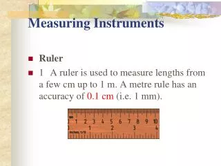
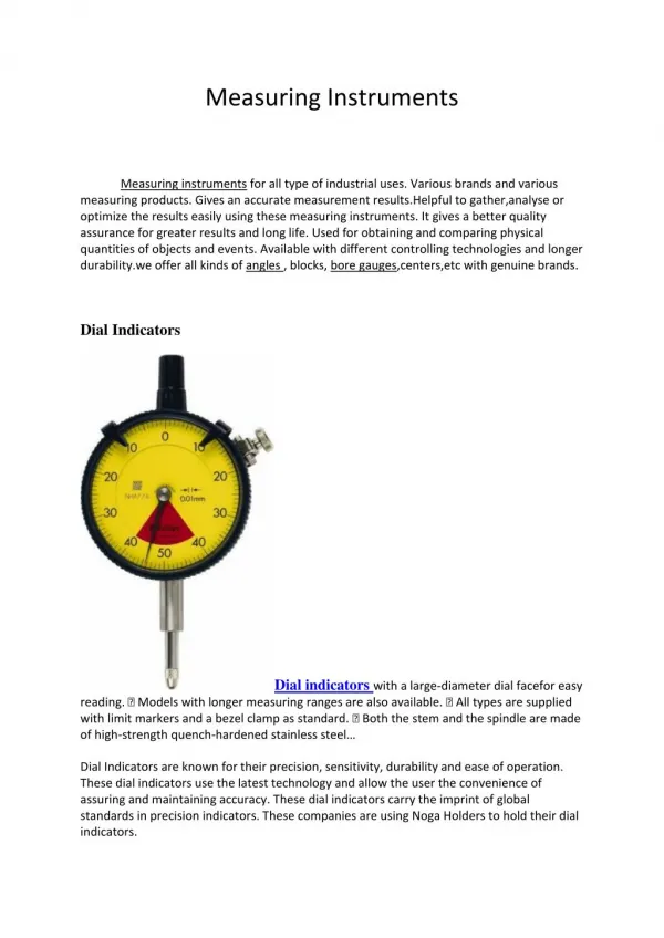
CLASSIFICATION OF SECONDARY INSTRUMENTS • Indicating Instruments: It indicate the magnitude of an electrical quantity at the time when it is being measured. The indications are given by a pointer moving over a graduated dial.
CLASSIFICATION OF SECONDARY INSTRUMENTS • Recording Instruments: The instruments which keep a continuous record of the variations of the magnitude of an electrical quantity to be observed over a defined period of time.
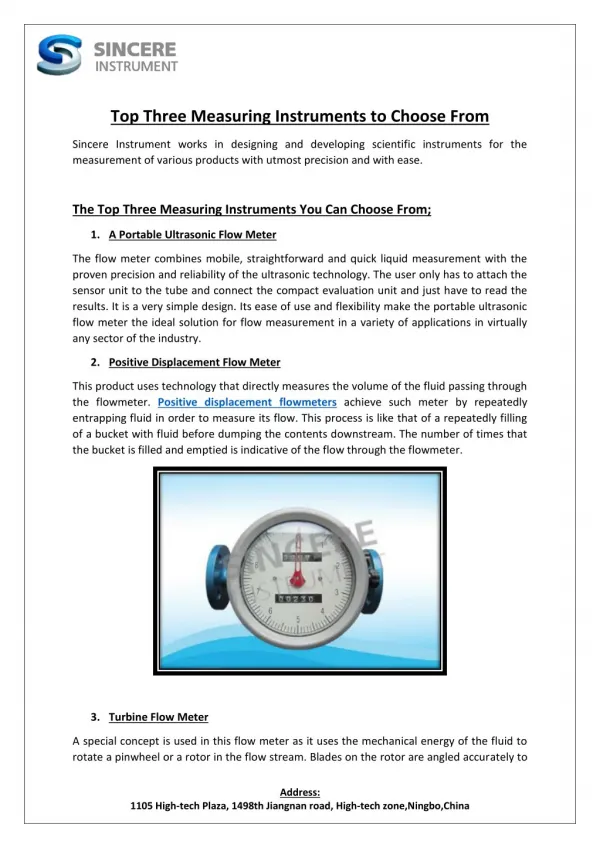
CLASSIFICATION OF SECONDARY INSTRUMENTS • Integrating Instruments: The instruments which measure the total amount of either quantity of electricity or electrical energy supplied over a period of time. For example energy meters.
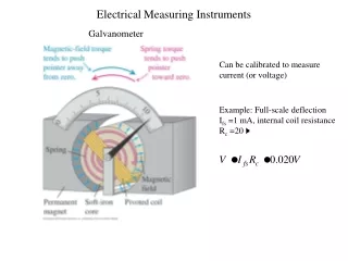
ESSENTIALS OF INDICATING INSTRUMENTS A defined above, indicating instruments are those which indicate the value of quantity that is being measured at the time at which it is measured. Such instruments consist essentially of a pointer which moves over a calibrated scale & which is attached to a moving system pivoted in bearing. The moving system is subjected to the following three torques: 1. A deflecting ( or operating) torque; 2. A controlling ( or restoring) torque; 3. A damping torque.
DEFLECTING TORQUE • The deflecting torque is produced by making one of the magnetic, heating, chemical, electrostatic and electromagnetic induction effect of current or voltage and cause the moving system of the instrument to move from its zero position. • The method of producing this torque depends upon the type of instrument.
CONTROLLING TORQUE • The magnitude of the moving system would be some what indefinite under the influence of deflecting torque, unless the controlling torque existed to oppose the deflecting torque. • It increases with increase in deflection of moving system. • Under the influence of controlling torque the pointer will return to its zero position on removing the source producing the deflecting torque. • Without controlling torque the pointer will swing at its maximum position & will not return to zero after removing the source.
Controlling torque is produced either by spring or gravity control. Spring Control: • When the pointer is deflected one spring unwinds itself while the other is twisted. This twist in the spring produces restoring (controlling) torque, which is proportional to the angle of deflection of the moving systems.
Gravity Control • In gravity controlled instruments, a small adjustable weight is attached to the spindle of the moving system such that the deflecting torque produced by the instrument has to act against the action of gravity. • Thus a controlling torque is obtained. This weight is called the control weight. Another adjustable weight is also attached is the moving system for zero adjustment and balancing purpose. This weight is called Balance weight.
DAMPING TORQUE • We have already seen that the moving system of the instrument will tend to move under the action of the deflecting torque. • But on account of the control torque, it will try to occupy a position of rest when the two torques are equal and opposite. • However, due to inertia of the moving system, the pointer will not come to rest immediately but oscillate about its final deflected position as shown in figure and takes appreciable time to come to steady state. • To overcome this difficulty a damping torque is to be developed by using a damping device attached to the moving system.
DAMPING TORQUE • The damping torque is proportional to the speed of rotation of the moving system, that is • Depending upon the degree of damping introduced in the moving system, the instrument may have any one of the following conditions as depicted in above graph.
DAMPING TORQUE • Under damped condition: The response is oscillatory 2. Over damped condition: The response is sluggish and it rises very slowly from its zero position to final position. 3. Critically damped condition: When the response settles quickly without any oscillation, the system is said to be critically damped. The damping torque is produced by the following methods: 1.Air Friction Damping2.Fluid Friction Damping 3.Eddy Current Damping4.Electromagnetic Damping
TYPES OF AMMETERS & VOLTMETERS • Moving Iron Type Meters (AC & DC); a) Attraction type, b) Repulsion type. 2) Moving Coil Type Meters (AC & DC); a) Permanent Magnet type, b) Electrodynamic or Dynamometer. • Hot Wire Type (AC & DC); • Induction Type (AC & DC); a) Split phase, b) Shaded Pole type. • Electrostatic Type for Voltmeters Only;
Moving-iron instrument • An attraction type of moving-iron instrument is shown diagrammatically in Figure. When current flows in the solenoid, a pivoted soft-iron disc is attracted towards the solenoid and the movement causes a pointer to move across a scale. • In the repulsion type moving-iron instrument shown diagrammatically in Figure, two pieces of iron are placed inside the solenoid, one being fixed, and the other attached to the spindle carrying the pointer.
Moving-Coil instrument • There are two types of moving coil instruments namely, permanent magnet moving coil type which can only be used for direct current, voltage measurements. • The dynamometer type which can be used on either direct or alternating current, voltage measurements.
PERMANENT MAGNET MOVING COIL “The principle operation of PMMC is based upon the principle of current carrying conductor is placed in a magnetic field it is acted upon by force which tends to move it.”
DYNAMOMETER • This instrument is suitable for the measurement of direct and alternating current, voltage and power. • The deflecting torque in dynamometer is relies by the interaction of magnetic field produced by a pair of fixed air cored coils and a third air cored coil capable of angular movement and suspended within the fixed coil.
HOT WIRE TYPE • It is based on the heating effect of current. • It consist of platinum-iridium (it can withstand oxidation at high temperatures) wire. • When current is through wire, it expands according to I2R formula. • This produces sag in the wire and pointer is attached with this wire which in result deflects.
INDUCTION TYPE INSTRUMENT • Such instruments are suitable for ac measurements only in these instruments the deflecting torque is produced by the eddy currents induced in an aluminum or copper disc or drum by the flux created by an electro-magnet. • The main advantages of such instruments are that (i) a full scale deflection can be obtained giving long and open scale (ii) the effect of stray magnetic field is small; (iii) damping is easier and effective.
INDUCTION TYPE INSTRUMENT • These instruments have got some serious disadvantages (i) The greater deflection causes more stresses in the control springs. (ii) Variation in supply frequency and temperature may cause serious errors unless compensating device is employed. (iii) These instruments are costlier and consume more power • Such instruments are mostly used as watt-meters or energy meters.
INDUCTION TYPE INSTRUMENT • Induction type wattmeter consists of two laminate electromagnets known as shunt electromagnet and series electromagnet respectively. • Shunt magnet is excited by the current proportional to the voltage across load flowing through the pressure coil and series magnet is excited by the load current flowing through the current coil. • A thin disc made of Cu or Al, pivoted at its centre, is placed between the shunt and series magnets so that it cuts the flux from both of the magnets.
INDUCTION TYPE INSTRUMENT • The deflection torque is produced by interaction of eddy current induced in the disc and the inducing flux in order to cause the resultant flux in shunt magnet to lag in phase by exactly 90° behind the applied voltage. • One or more copper rings, known as copper shading bond are provided on one limb at the shunt magnet. • Correct disappointed between shunt and series magnet fluxes may be attained by adjusting the position of copper shading bonds.The pressure coil circuit of induction type instrument is made as inductive as possible so that the flux of the shunt magnet may lag by 90° behind the applied voltage.