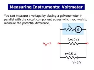
Measuring Instruments
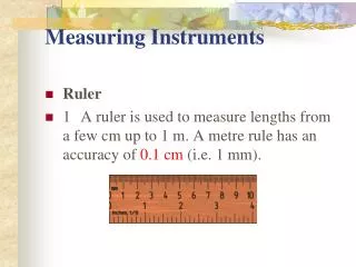
Measuring Instruments. Ruler 1 A ruler is used to measure lengths from a few cm up to 1 m. A metre rule has an accuracy of 0.1 cm (i.e. 1 mm). Measuring Instruments. Ruler 2 Precautions to be taken when using a ruler:

Measuring Instruments
E N D
Presentation Transcript
Measuring Instruments • Ruler • 1 A ruler is used to measure lengths from a few cm up to 1 m. A metre rule has an accuracy of 0.1 cm (i.e. 1 mm).
Measuring Instruments • Ruler • 2 Precautions to be taken when using a ruler: • (a) Ensure that the object is in contact with the ruler to avoid inaccurate readings. • (b) Avoid parallax errors.
Measuring Instruments • Ruler • Parallax errors in measurement arise as a result of taking a reading, with the eye of the observer in the wrong position with respect to the scale of the ruler. Figure 1.7 shows the correct position of the eye when reading the scale. Error = 0.1 cm Error = 0.1 cm
Measuring Instruments • Ruler • (c) Avoid zero and end errors. • The ends of a ruler, which may be worn out, are a source of errors in measurement. Thus it is advisable to use the division mark `1' of the scale as the zero point when taking a measurement.
Measuring Instruments • Ruler • (c) Length of the block, l =3.2cm-1.0cm = 2.2 cm
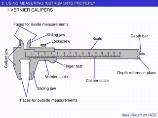
Measuring Instruments Vernier Caliper • 1 Lengths smaller than 1 mm can be measured with the help of an instrument called a vernier caliper.
Measuring Instruments • Vernier Caliper • 2 A vernier caliper is used to measure an object with dimensions up to 12 cm with an accuracy of 0.01 cm.
Measuring Instruments • Vernier Caliper • 3 There are two pairs of jaws, one is designed to measure linear dimensions and external diameterswhile the other is to measure internal diameters.
Measuring Instruments • Vernier Caliper • 4. To measure with a vernier caliper, slide the vernier scale along the main scale until the object is held firmly between the jaws of the caliper. The subsequent steps are as follows.
Measuring Instruments • Vernier Caliper • (a)The reading on the main scale is determined with reference to the `0' mark on the vernier scale. The reading to be taken on the main scale is the mark preceding the Figure 1.10 shows that the '0' mark on the vernier scale lies between 3.2 cm and 3.3 cm. The reading to be taken on the main scale is 3.2 cm (the `0' mark on the vernier scale acts as a pointer). 1
Measuring Instruments • Vernier Caliper • (b) The reading to be taken on the vernier scale is indicated by the mark on the vernier scale which is exactly in line or coincideswithany main scale division line. Figure 1.10 shows that the fourth markon the vernier scale is exactly in line with a mark on the main scale. Thus the second decimal reading of the measurement is: • Vernier scale reading = 4 x 0.01 cm • = 0.04 cm 2
Measuring Instruments 0.04 • Vernier Caliper • (c) The reading of the vernier caliper is the result of the addition of the reading on the main scale to the reading on the vernier scale. 3.2
Measuring Instruments 0.04 • Vernier Caliper • (c) The reading of the vernier caliper is the result of the addition of the reading on the main scale to the reading on the vernier scale. • Caliper reading = Main scale Reading + Vernier scale reading • Thus the reading of the vernier caliper in Figure 1.10 is • = 3.2 + 0.04 = 3.24 cm 3.2
Measuring Instruments • Vernier Caliper • 5. A vernier caliper has a zero error if the `0' mark on the main scale is not in line with the '0' mark on the vernier scale when the jaws of the caliper are fully closed
Measuring Instruments • Vernier Caliper • (a) Positive zero error • Zero error = +0.04 cm. {0.40 – 0.36=+0.04cm}
Measuring Instruments 0.02cm 0.70 cm 0.72 cm
Measuring Instruments • Vernier Caliper (b) Negative zero error • Zero error = -0.02 cm.
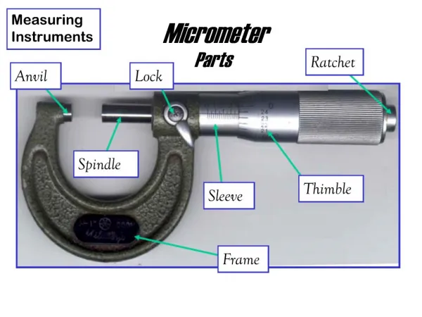
Measuring Instruments • Micrometer Screw Gauge 1 A micrometer screw gauge is used to measure small lengths ranging between 0.10 mm and 25.00 mm.
Measuring Instruments • Micrometer Screw Gauge 2 This instrument can be used to measure diameters of wires and thicknesses of steel plates to an accuracy of 0.01 mm.
Measuring Instruments • Micrometer Screw Gauge 3 The micrometer scale comprises a main scalemarked on the sleeve and a scale marked on the thimble called the thimble scale.
Measuring Instruments • Micrometer Screw Gauge 4 The difference between one division on the upper scale and one division on the lower scale is 0.5 mm.
Measuring Instruments Micrometer Screw Gauge 5 The thimble scale is subdivided into 50 equal divisions. When the thimble is rotated through one complete turn, i.e. 360, the gap between the anvil and the spindle increases by 0.50 mm.
Measuring Instruments Micrometer Screw Gauge 6 This means that one division on the thimble scale is = 0.01 mm.
Measuring Instruments Micrometer Screw Gauge 7 When taking a reading, the thimble is turned until the object is gripped very gently between the anvil and the spindle.
Measuring Instruments Micrometer Screw Gauge 8 The ratchet knob is then turned until a `click' sound is heard.
Measuring Instruments Micrometer Screw Gauge 9 The ratchet knob is used to prevent the user from exerting undue pressure.
Measuring Instruments Micrometer Screw Gauge 10 The grip on the object must not be excessive as this will affect the accuracy of the reading.
Measuring Instruments Micrometer Screw Gauge 11 Readings on the micrometer are taken as follows. (a) The last graduation showing on the main scale indicates position between 2.0 mm and 2.5 mm. Thus the reading on the main scale is read as 2.0 mm.
Measuring Instruments Micrometer Screw Gauge 11 Readings on the micrometer are taken as follows. (b) The reading of the micrometer screw gauge is the sun of the main scale reading and the thimble scale reading which is: • 2.0 + 0.22 =2.22 mm
Measuring Instruments Micrometer Screw Gauge 11 Readings on the micrometer are taken as follows. (b) The reading on the thimble scale is the point where the horizontal reference line of the main scale is in line with the graduation mark on the thimble scale Figure 1.15(b) shows this to be the 22nd mark on the thimble scale, thus giving a reading of 22 x 0.01 mm = 0.22 mm.
Measuring Instruments Micrometer Screw Gauge 12 Readings on the micrometer are taken as follows. (a) Positive zero error • In Figure 1.16, the horizontal reference line in the main scale is in line with the 4th division mark, on the positive side of the `0' mark, on the thimble scale. The error of +0.04 mm must be subtracted from all readings taken. • Zero error = +0.04 mm
Measuring Instruments Micrometer Screw Gauge 13(b) Negative zero error In Figure 1.17, the horizontal reference line on the main scale is in line with the 3rd division mark, below the `0' mark of the thimble scale. Zero error = -0.03 mm
Chapter 1 1.5 ANALYSING SCIENTIFIC INVESTIGATION
1.5 ANALYSING SCIENTIFIC INVESTIGATION • 1. The investigative procedure begins with the following steps: • Making an inference • To interpret or explain what is being observed. It is also an early conclusionbased on observation.
1.5 ANALYSING SCIENTIFIC INVESTIGATION • Determining the variables • A variable is a physical quantity which varies/changes during the course of a scientific investigation.
1.5 ANALYSING SCIENTIFIC INVESTIGATION • In a scientific investigation, there are 3 different types of variables, namely: • (a) Manipulated variable • • It is a physical quantity which is fixed in an experiment. • (b) Responding variable • • It is a physical quantity which depends on the independent variable. • (c) Constant variable • • It is a physical quantity which is fixed while an experiment is being carried out.
1.5 ANALYSING SCIENTIFIC INVESTIGATION • Making a hypothesis • It is a clarification/explanation regarding the relationship between the manipulated variable and the responding variable when all other variables are kept constant. • A hypothesis must be proven correct after an experiment is carried out.
1.5 ANALYSING SCIENTIFIC INVESTIGATION • Controlling the variable • The experiment must be conducted in an appropriate place so as not to influence the variables.
1.5 ANALYSING SCIENTIFIC INVESTIGATION • Planning the investigative procedure/method • Covers the choice and arrangement of the apparatus together with the work procedure being followed/ conducted.
1.5 ANALYSING SCIENTIFIC INVESTIGATION • Collecting data in tabular form • Data in the same strips (i.e., rows and columns) must have the same units and the same number of decimal places (ie., data must be consistent). • For example:
1.5 ANALYSING SCIENTIFIC INVESTIGATION • 1. The investigative procedure begins with the following steps: • Collecting data in tabular form • For example:
1.5 ANALYSING SCIENTIFIC INVESTIGATION • Interpreting the data • It is a result/decision that is made by way of the experiment.
1.5 ANALYSING SCIENTIFIC INVESTIGATION • Making a conclusion • It is a record that is made regarding an information that is being studied based on the aim of the experiment. • The conclusion which is made is based on the shape of the graph that is plotted and also on the value(s) of the quantities obtained through calculation using a formula.
1.5 ANALYSING SCIENTIFIC INVESTIGATION • Making a complete report of an experiment • A complete report of an experiment must cover all the following aspects: • • Problem statement • • Inference • • Hypothesis • • Aim of experiment • • Variables of the experiment • • Arrangement of apparatus/Materials used
1.5 ANALYSING SCIENTIFIC INVESTIGATION • Making a complete report of an experiment • • Experimental procedure - including the method for controlling the manipulated and responding variables. • • Tabulating data • • Analyzing data • • Making a conclusion • • Data tabulation • • Data analysis
1.5 ANALYSING SCIENTIFIC INVESTIGATION • Experiment 1.1 • To Study The Relationship Between The Length Of A Pendulum And The Period Of Oscillation of The Pendulum • Problem Statement • How can the period of oscillation of a pendulum be determined?
1.5 ANALYSING SCIENTIFIC INVESTIGATION • Experiment 1.1 • To Study The Relationship Between The Length Of A Pendulum And The Period Of Oscillation of The Pendulum • Hypothesis • As the length of the pendulum increases, its period of oscillation increases.
1.5 ANALYSING SCIENTIFIC INVESTIGATION • Variables • (a) Manipulated : Length of pendulum • (b) Responding : Period of oscillation • (c) Constant: Amplitude of oscillation, mass of pendulum bob (or weight) and acceleration due to gravity.
1.5 ANALYSING SCIENTIFIC INVESTIGATION • Experiment 1.1 • Apparatus/Materials Used • Pendulum bob, a 100cm length of thread, metre rule, 2 small pieces of wood, retort stand and a stop-watch.
1.5 ANALYSING SCIENTIFIC INVESTIGATION • Experiment 1.1 • To Study The Relationship Between The Length Of A Pendulum And The Period Of Oscillation of The Pendulum • Procedure